
- Applicated Security Technologies Automobile Alarm User Manual

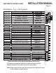
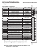
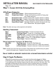

Wiring Diagram - 11 pin + 4 pin Connectors
BLUE
GREEN
RED
RED
YELLOW
Starter Output
Heater/Acc Output
Power Input
Ignition Output
Selectable Output
Power Input
30amp Output
30amp Output
30amp Input
30amp Input
30amp Output
30amp Output
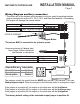
* These connections are for manual transmission vehicles only!
“M” models must always be installed into manual transmission vehicles.
Manual transmission “M” modules are cased in Yellow plastics.
Note: 250ma outputs are low current and may require the installation of a relay
for the activation of optional features.
1
5
3
2
4
6
1
2
3
4
5
6
7
8
9
10
11
15
12
13
14
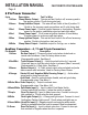
WHITE
Factory Re-arm Output
Starter kill & Anti-Grind Output
Factory Disarm Output
Trunk Release Output
(+) Siren Output
(+)10amp Park Light Output
Negative Door Pin Input
Negative Park Brake Input
Positive Door Pin Input
Hood Pin Switch Input
System Ground Input
YELLOW
WHITE/BLUE
BLACK
BROWN
RED/WHITE
WHITE
GREEN/WHITE
(-)250ma Output
ORANGE
(-)250ma Output
(-)250ma Output
(-)250ma Output
Positive Output
Negative Input
Negative Input
Positive Input
Positive Output
Negative Input
Negative Input
BLACK/WHITE*
GREEN*
PURPLE*
Brake Switch Input
Tach Detection Input
Diesel Glow Plug Input
(-)When Running Output
BLUE/WHITE
PINK
White/Violet
BLUE
Negative Output
(+ or -) Input
Positive Input
A/C Input
2WAY REMOTE STARTER/ ALARM INSTALLATION MANUAL
Page 5