
- Applicated Security Technologies Automobile Alarm User Manual

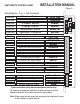
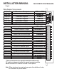
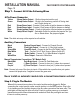

Wiring Diagram auxiliary connectors
Door lock output
Door unlock output
(-) When Running
Low Current (-) Output
Low Current (+) Output
Door lock module output only*
ACTIVE RF ANTENNA**
(-) 500ma Output
(-) 250ma Output
(-) 250ma Output
(-) 500ma Output
(+) 500ma Output
12
3
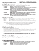
The jumpers control the output from the WHITE wire on the 6- pin harness. This is an
30amp relayed output. Place the jumpers in the following order to change the output.
If the jumper is in position #1 the output on the white wire will be 2nd Starter
If the jumper is in position #2 the output on the white wire will be 2nd Accessory
If the jumper is in position #3 the output on the white wire will be 2nd Ignition
*The factory default setting of the selectable output jumper is position #3.
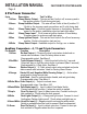
Output on White wire Jumper position
Second Starter Position 1
Second Accessory Position 2
Second Ignition Position 3
Status Led’s
Program Button
**The antenna MUST be connected for the system to operate
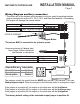
* The centre pin of the keyless entry harness is not to be used for anything besides
plug-in devices such as the VP-1, DL-3, DL-7 and Data Bus Modules. Overloading
this output will damage the remote starter.
1
2
3
1
2
3
4
1
2
3
1
2
*Temperature Sensor (LT Models Only)
*Input Trigger To Start 1350 Series
*Not available on 1250 Series
Green
White/Violet
Blue
Black
Red
Red
Jumpers
Page 7
2WAY REMOTE STARTER/ALARM INSTALLATION MANUAL