562600-000, Issue1.
This guide describes operation of the PROLEC PME LIFTING AND MACHINE ENVELOPE SAFETY SYSTEM FOR CONSTRUCTION PLANT Model covered : PART No.
Table of contents 1 Use of this Document 7 2 Notices 7 3 System Identification 8 4 Operating and Restriction Situation Recommendations 9 4.1 RCC - MEC Override 9 5 Operating Instructions 10 5.1 Power Up 10 5.2 Using the Display 11 5.3 User Login 12 5.4 User Logout 13 5.5 Supervisor Keyswitch 13 6 Top Menu 13 7 Rated Capacity Controller 14 7.1 Introduction 14 7.2 Operation within the Safe Working Load 15 7.3 Barred, Duties, Warnings and Interlocks 15 7.
Table of contents (continued) 7.7 Lift Mode Menu 8 18 7.7.1 Lifting Point Selection 18 7.7.2 Lifting Mode - Non Lifting Mode 19 7.7.3 Tandem Lifting Mode 20 7.7.4 LUL Lifting Mode 21 7.8 Lifting Duty Safety Factors 22 7.9 Load Chart Menu 23 7.10 Working Area Indication 24 7.11 In Gauge Indicator 25 Envelope Monitoring 26 8.1 Height Limit 26 8.1.1 Height Limits Menu 27 8.1.2 Height Limit Setting - Known Height 28 8.1.3 Height Limit Setting - Using Current Highest Point 29 8.1.
Table of contents (continued) 9 System Messages 39 9.1 On Screen Safety Messages 39 9.2 On Screen Component Error Messages 40 9.3 On Screen ALO Component Error Messages 41 9.4 LED and Internal Alarm Warnings 42 10 Daily checks 42 11 Repair 42 12 Test / Diagnostics 43 12.1 Relay Function Test 43 12.2 Sensor Information 44 12.3 Blue and Amber lamp, Alarm and LED function 44 13 System Information 45 14 Display Settings 45 14.1 Day / Night Mode 46 14.
Table of contents (continued) 15.1.2 Edit User Details 49 15.1.3 Select User to Delete 50 15.1.4 Edit User Access Code 50 15.1.5 Enable / Disable Users 51 16 Taking Product out of Operation 51 17 Service and Repair 51 17.
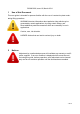
562600-000, Issue1.0, March 2014 1 Use of this Document This user guide is intended for persons familiar with the use of construction plant undertaking lifting operations. WARNING denotes information about particular risks which may be generated by certain applications, by using certain fittings, and about additional protective measures which are necessary for such applications.
562600-000, Issue1.0, March 2014 3 System Identification The PMERail Ultra system provides two primary safety functions 1. Lifting Stability 2. Machine Envelope Monitoring Both safety functions are achieved through real time monitoring some or all of the machine’s moving parts ( booms, other articulations, turret etc ) and its environment ( ground pitch and inclination, load etc) and actively determining the safety of the current operation where appropriate limits have been set.
562600-000, Issue1.
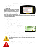
562600-000, Issue1.0, March 2014 5 Operating Instructions 5.1 Power Up PMERail automatically powers up when the machines ignition is switched on. The in-cab display incorporates a 4.3” high resolution LCD display and is controlled with three buttons at each side. Three status LEDs and an internal alarm provide further information. The display is secured to the machine using a flexible ball mounting allowing easy adjustment for personal viewing preference. Upon starting up: 1.
562600-000, Issue1.0, March 2014 5.2 Using the Display The display is operated by using the buttons adjacent to a function icon. The buttons can open a sub menu, turn a function ON or OFF, set a value and toggle through multiple screens. No one button has a single function. The button icon will turn black/purple when the button has been activated. Note that the image of the machine on the left is fixed and does not follow the movement of the machine.
562600-000, Issue1.0, March 2014 5.3 User Login If PMERAIL has been configured to work with the Operator Database, the system will prompt for a user login pass code. Select the user name required and the login code screen will appear. Moves highlighter UP Exit Login Select highlighted name to open the login code screen below Moves highlighter DOWN Using the arrow buttons enter a valid pass code. The previous pass code digits will be replaced with a star as the code is entered.
562600-000, Issue1.0, March 2014 5.4 User Logout If a user is logged in, they can select the logout screen by holding an exit key button down for three seconds. Cancel to stay logged in Confirm logout Once log off has been confirmed, the login screen will be automatically displayed. Press the RED CROSS button to stay logged in, the screen will return to that previously shown. 5.5 Supervisor Key Switch The supervisor keyswitch must be in the SET position to access the lift mode functions, see section 7.
562600-000, Issue1.0, March 2014 7 Rated Capacity Controller 7.1 Introduction PMERail has been designed to meet Network Rail requirements for the provision of rated capacity indicators and ensures that the maximum lifting capacity over the range of a machine working envelope can be utilised. The system will default to Lifting Mode when started up or when the bogies are deployed. See section 4 for operating advice when using construction plant as a crane.
562600-000, Issue1.0, March 2014 7.2 Operation within the Safe Working Load With Lifting Mode active, the Load on Hook, current lifting point, current duty, lifting point radius and the maximum safe working load for that radius are shown. If the load is less than 95% of the maximum safe working load The load capacity indicator will be green The green LED will be lit 7.
562600-000, Issue1.0, March 2014 7.5 Stability Overload Control Where an overload condition occurs the machine hydraulics will be locked to prevent any further dangerous movements. Only those movements that allow safer operation remain active, all slewing is prevented. The radius cannot be increased and the load cannot be raised. The internal and external alarms will sound in conjunction with visual indicators on the display.
562600-000, Issue1.0, March 2014 7.6 Overload / Hydraulic Limitation Control Override 7.6.1 Soft Override Three seconds after overload has occurred, a soft override button will become available in the top menu with the supervisor keyswitch is in the SET position, see sections 5.5 and 7.6.1. If the soft override function is utilised, the machine hydraulics will be re-enabled.
562600-000, Issue1.0, March 2014 7.7 Lift Mode Menu The Lifting Mode menu has various features which may be available if configured at installation. If only one lifting point has been calibrated, the lifting point button will not be displayed. Lift Mode selection Lifting point selection Displays load chart(s) Exit to previous screen 7.7.1 Lifting Point Selection PMERail can be configured for more than one lifting point.
562600-000, Issue1.0, March 2014 7.7.2 Lifting Mode - Non Lifting Mode When the machine is not being used for lifting operations it can be put into ‘Non Lifting Mode’. This is available from the Lifting Mode screen. When in Non Lifting Mode, the system still monitors all machine activity and safety status but will NOT warn of overload or impose any form of overload hydraulic control, the system will continue to monitor back stability conditions.
562600-000, Issue1.0, March 2014 7.7.3 Tandem Lifting Mode PMERAIL can be configured for tandem lifting. If tandem lifting has been calibrated, it will be manually selected via the lift Mode menu. Once selected, the blue lamp will flash to indicate the system is in tandem lifting mode. The Supervisor keyswitch must be positioned in the SET position to select or cancel this feature, see section 5.5 for further details.
562600-000, Issue1.0, March 2014 7.7.4 LUL Lifting Mode PMERail can be configured for LUL mode. If LUL has been calibrated, it will be manually selected via the lift Mode menu. The Supervisor keyswitch must be positioned in the SET position to select or cancel this feature, see section 5.5 for further details.
562600-000, Issue1.0, March 2014 7.8 Lifting Duty Safety Factors The maximum safe working load will appear at the top right of the screen and is stated in TONNES. This maximum load is for the currently active lifting duty / lifting point. Lifting duties are automatically selected using a combination of chassis status, axle lock status, slew angle, chassis angle and switch inputs. Altering the duty will not affect the current lifting point selected, see section 7.7.1.
562600-000, Issue1.0, March 2014 7.9 Load Chart Menu PME can display the load chart for the currently selected lifting duty and lifting point. *If the machine is equipped with a hydraulically adjustable boom, both maximum and minimum charts will be available via this button. Hydraulically adjustable booms allow the machine to reach the same point in space (i.e. height and radius combination) with a variety of different equipment angles.
562600-000, Issue1.0, March 2014 7.10 Safe Working Area Indication Safe working area indication displays in real time the where a load can be safely moved using the plan view. This feature will be available if it has been activated at calibration. With Safe Working Indication ON: The Green area indicates the safe zone The Hatched area indicates the hazard zone Any green area is safe and any hatched area is unsafe.
562600-000, Issue1.0, March 2014 7.11 In Gauge Indicator If the machine is on-rail, within the Wa6 gauge and the oscillating axle is unlocked, the In Gauge icon will turn from a RED CROSS to a GREEN TICK and the In Gauge button will appear in the top menu, press to motion to cut all services for safe travel. The GREEN TICK symbol indicates that the right and left corners of the counterweight, bucket pin and the highest point of the machine are within the W6a gauge dimensions.
562600-000, Issue1.0, March 2014 8 Envelope Monitoring PMERail Ultra is configured for Machine Envelope Control (MEC) only. MEC will warn and prevent equipment motion in a limit state. MEC is achieved by interacting with the machines hydraulics, this allows motion to be cut to any section of equipment that has reached a restriction but allow other sections to operate unhindered unless they too reach the set restriction, see section 8.4 for monitored points on the machine.
562600-000, Issue1.0, March 2014 8.1.1 Height Limit Menu A height limit can be set by entering a known height on the keypad or by manually moving the machine to the desired limit. Current highest point. Only displayed if a height limit is set.
562600-000, Issue1.0, March 2014 8.1.2 Height Limit Setting - Known Height A known limit can be entered into the display: Enter a value Exit to previous menu Step One Press the ’Enter a value’ button Cancel without change Moves highlighter to left / Hold to delete digit Accept displayed value Increases highlighted digit Moves highlighter to right / Hold to delete digit Decreases highlighted digit Step Two Set a limit and press Green TICK to accept.
562600-000, Issue1.0, March 2014 8.1.3 Height Limit Setting - Using Current Highest Point The highest point of the machine can be used to create a height limit: Move equipment to required height limit and press this button Step One Move the equipment to the required height limit and press the ‘Set using highest point of equipment’ button Exit without change Accept the value shown Step Two Check the limit and press Green TICK to accept.
562600-000, Issue1.0, March 2014 8.1.4 Machine Envelope Controller (MEC) - Height If any of the equipment enters the approach limit* The amber LED will be lit The internal alarm will sound The message shown here will be displayed. MEC systems will cut motion to any section of equipment that has reached a limit but allow other sections to operate unhindered unless they too reach the set limit. The safe directional indicators will be red.
562600-000, Issue1.0, March 2014 8.2 Slew Limit 8.2.1 Slew Limits Menu A virtual wall slew limit can be set entering a known distance on the keypad or by moving the virtual wall on the screen using the arrow buttons to the desired limit. With a slew limit set, the screen will display a hatched area on the plan view.
562600-000, Issue1.0, March 2014 8.2.2 Virtual Wall Limit Setting - Dial in a value A virtual wall can be set on either side of the machine to a desired distance by either dialling in a value. The value displayed is measured from the centre of the machine. Do not travel once a slew limit has been set.
562600-000, Issue1.0, March 2014 Cancel without change Moves highlighter to left / Hold to delete digit Accept displayed value Increases highlighted digit Moves highlighter to right / Hold to delete digit Decreases highlighted digit Step four Use the UP and DOWN arrows to increase and decrease the highlighted number. Use the LEFT and RIGHT arrows to move the highlighter to the left and to the right. Press the GREEN TICK to accept the displayed value.
562600-000, Issue1.0, March 2014 8.2.3 Virtual Wall Limit Setting - Manually set a limit A virtual wall can be set on either side of the machine to a desired distance by using the directional arrows to manually move the limit. The limit displayed is measured from the centre of the machine. Do not travel once a slew limit has been set.
562600-000, Issue1.0, March 2014 Safe Directional indicators. The triangles indicate if it is safe GREEN, or unsafe RED to slew or move a particular articulation. Virtual wall limit The Virtual wall will be shown on the main screen. Once slew limits are set, the internal alarm will sound and the RED LED will light if the equipment exceeds the either limit. Always check that the slew limit activates at the set point. The limits cannot be deactivated if in the alarm state.
562600-000, Issue1.0, March 2014 8.2.4 Machine Envelope Controller (MEC) - Virtual Wall PMERail Ultra 8.2.4.1 PMERail Ultra Virtual Wall Limitation Control PMERail Ultra complies with NR MDL/004 ISSUE 2. slew limits requirements. Therefore with a virtual wall slew limit active, as in addition to standard slew limit function (see section 8.2.4.
562600-000, Issue1.0, March 2014 8.2.4.2 Machine Envelope Controller (MEC) - Virtual Wall If any of the equipment enters the approach limit* The amber LED will be lit The internal alarm will sound The message shown here will be displayed. MEC systems will cut motion to any section of equipment that has reached a limit but allow other sections to operate unhindered unless they too reach the set limit. If the equipment reaches the limit, the appropriate motion will be controlled.
562600-000, Issue1.0, March 2014 8.3 Equipment Position measurement PMERail measures equipment pin positions using equipment mounted angle sensors. All positions are corrected for chassis pitch (rail gradient), roll (rail cant) and slew angle. The radius displayed on the operators screen represents the current lifting point and the height represents the tool pin height. Shown without hitch.
562600-000, Issue1.0, March 2014 9 System Messages 9.1 On Screen Safety Messages Approaching max height Highest point of equipment within *0.5m of set limit Maximum height exceeded Equipment has reached/exceeded set limit ALO Controlling Slew PMERail is controlling slew movement toward the slew limit Approaching Slew limit Equipment within *10 degrees or 0.
562600-000, Issue1.0, March 2014 9.2 On Screen Component Error Messages PMERail continuously monitors the presence and condition of it’s system components. If any sensor, input, output, or other component fails, an error message will appear along the bottom of the display. In the event of a failure, ALL motion control relays will be operated, the cab mounted blue lamp will indicate that the RCI is NOT active, the display red LED will flash and the internal and external alarms will sound.
562600-000, Issue1.0, March 2014 9.3 On Screen ALO Component Error Messages PMERail Max and Ultra continuously monitors the presence and condition of the ALO slew components. If any sensor, input, output, or other component fails, an error message will appear along the bottom of the display. In the event of a failure, ALL motion control relays will be operated, the cab mounted blue lamp will indicate that the RCI is NOT active, the display red LED will flash and the internal and external alarms will sound.
562600-000, Issue1.0, March 2014 9.4 LED and Internal Alarm Warnings The table below shows the state of the three LEDs on the display and the internal alarm with respect to system status.
562600-000, Issue1.0, March 2014 12 Test / Diagnostics The system test function is available from the top menu screen. This feature allows the system functions to be verified and basic trouble-shooting to be performed. In this mode, the amber LED will flash to indicate the system is in maintenance mode. The system will continue to monitor any active limits to monitor machine safety status if in lift mode. Alarm conditions and warnings / controls will be issued as normal.
562600-000, Issue1.0, March 2014 12.2 Sensor Information Displays the systems sensor information in bar or degrees. Use the Actual column for direct comparison. The status column shows the health of each sensor. Base Pitch = Pitch Angle Base Roll = Pitch Angle Boom Base Piston = Piston Pressure Boom Base Rod = Rod Pressure Boom AS7/10 = Boom angle Artic AS7/10 = Artic angle Arm AS7/10 = Arm angle Platform = Slew angle Linkage AS7 = Tipping link /Hitch Angle Exit to previous menu 12.
562600-000, Issue1.0, March 2014 13 System Information Information regarding the system can be found from this menu. LOLER information Software Version Machine information License information Distributor information Exit to previous menu 14 Display Settings Information The display brightness, button click volume, background colour and the displayed machine can be adjusted from this menu.
562600-000, Issue1.0, March 2014 14.1 Day / Night Mode To make viewing of the display more comfortable at night, the display brightness can be switched to a preset ‘night mode’. The system will default to day mode on power up. Select day / night mode: Day mode ON Night mode ON Full display brightness Reduced display brightness 14.2 Select Display Machine An appropriate machine image for the display can be selected from this list.
562600-000, Issue1.0, March 2014 14.4 Select Language Select an appropriate language from the list. Moves highlighter UP Exit without change Accept highlighted language Moves highlighter DOWN 14.5 Select Screen background colour Different background colours, White, blue, cream and grey are available. Use this button to choose as required. 15 User Login 15.1 User Login manual Setup Allows access to edit user details. Requires supervisor access rights.
562600-000, Issue1.0, March 2014 15.1.
562600-000, Issue1.0, March 2014 15.1.2 Edit User Details Requires supervisor access rights.
562600-000, Issue1.0, March 2014 15.1.3 Select User to Delete Requires supervisor access rights. Moves highlighter UP Exit without change Delete highlighted Moves highlighter DOWN 15.1.4 Edit User Login Code Requires supervisor access rights.
562600-000, Issue1.0, March 2014 15.1.5 Enable / Disable Users Requires supervisor access rights Quick Select / deselect all Cancel without change Select / deselect Moves highlighter UP Select user(s) to be displayed on login screen Moves highlighter DOWN 16 Taking Product out of Operation Prolec Limited is committed to complying with the upcoming European Directive of RoHS (Restriction of Certain Hazardous Substances) and WEEE (Waste from Electrical and Electronic Equipment).
562600-000, Issue1.0, March 2014 18 Data Logger PMERail has two data-logging functions. The data logging icon appearis in the bottom left of the screen. The data can only be viewed by extracting it from the system, contact your service agreement holder or Prolec Ltd for further assistance. Where a data logging system is found not to be operational then the vehicle shall not be used until the fault is repaired and fully confirmed as operational.
562600-000, Issue1.
562600-000, Issue1.
562600-000, Issue1.0, March 2014 Appendix 1 Duty Numbering The duty number is made up of three values: Road/rail cant - active sector - Axle lock status i.e. 2BL will be rail (0-50mm cant), sector B, Axles Locked. Road/Rail Cant Levels The cant levels shown here are the default values. These can be adjusted as required during calibration. Cant measurement shown refers to the machine turret.
2600-000, Issue1.0, March 2014 Appendix 2 Interlocks 1. When the oscillating rail axle is locked the symbol shown here will appear on the display. If the interlock was configured during installation the forward and rear travel functions will be disabled when this symbol is visible. 2. When the oscillating rail axle is locked, PMERail will start to monitor the equivalent UNLOCKED duty.
562600-000, Issue1.0, March 2014 Prolec Ltd 25 Benson Road Nuffield Industrial Estate Poole England BH17 0GB Tel: +44 (0)1202 681190 E-mail: service@prolec.co.