
Specifications

E-24 Sun Enterprise 6500/5500/4500 Systems Reference Manual • April 1998
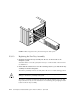
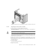
FIGURE E-14 Removing the Fan Tray from the Enterprise 4500 System
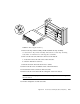
E.3.1.2 Replacing the Fan Tray Assembly
1. Carefully insert the fan tray assembly into the slot on the left side of the
Enterprise system.
Viewed from the rear of the system, the fan tray is on the left side of the enclosure.
See
FIGURE E-14.
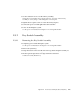
2. Ensure that the extraction lever is in the outward position as you slide the fan tray
assembly toward the centerplane.
The fan tray assembly will not seat fully unless the lever is in this starting position.
Caution – DO NOT FORCE the fan tray assembly into the slot; this can cause
damage to the fan tray assembly and system.
The fan tray assembly should insert and seat smoothly. If it binds, remove it, and
inspect the slot for any obvious obstructions. Do not damage the springfingers at the
bottom of the fan tray assembly.