
Specifications

Appendix E Non-Chassis Field Replaceable Units (FRUs) E-25
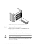
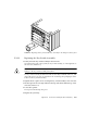
3. Use the extraction lever to seat the fan tray assembly.
Swing the lever inwards to the locked position. Do not press on the fan tray
assembly to seat it; doing so will damage the connector pins.
4. Tighten the two captive screws to secure the fan tray in place.
5. Connect the power cord and tighten the cable restrainer.
6. Power on the Enterprise system.
See the power on instructions in Chapter 11 “Powering Off and On.”
E.3.2 Key Switch Assembly
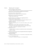
E.3.2.1 Removing the Key Switch Assembly
1. Completely power off the Enterprise system.
See the power off instructions in Chapter 11 “Powering Off and On.”
2. Remove the system key.
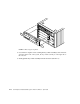
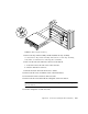
3. Grasp the bottom corners of both sides of the top bezel and pull it toward you.
4. Tilt the top bezel upward to a 45
o
angle and remove the bezel.
Set the bezel aside (
FIGURE E-15).