
Specifications


Chapter 3 CPU/Memory+ Boards and Components 3-11
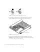
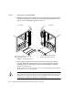
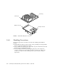
3. Push the board into the card cage, then simultaneously press both extraction
levers to seat the board on the centerplane.
Pushing both levers simultaneously avoids twisting the board and bending the
connector pins, and mates the board centerplane connector to the matching
receptacle on the centerplane. Do not press on board front panel to seat it—doing so
will damage the connector pins.
4. Mechanically lock the board to the system chassis by inserting a Phillips #1
screwdriver into each quarter-turn access slot and then turning to the locked
position (
FIGURE 3-3).
5. Once the board has been installed, a message similar to the following will be
displayed on the monitor (if the system is powered on):
Example depicts screen output when a new CPU/Memory+ board has been hot-
plugged into slot 6 of an operating Enterprise system:
This screen output indicates that the board has been detected by the system and is in
the low power mode. Additionally, any subsequent prtdiag(1M) output would
include information for board slot 6. Again, note that the system will not use the
new board until the system is rebooted.
6. Reboot the system now or schedule a later time to reboot when system disruption
will be minimized.
3.4.3 UltraSPARC II Modules
Each CPU/Memory+ board has four connectors for UltraSPARC II modules (up to
two modules per board, two connectors per module). For each module, there is a
connector with 144 pins and a connector with 288 pins (
FIGURE 3-8).
NOTICE: CPU Board Hotplugged into Slot 6
NOTICE: Board 6 is ready to remove