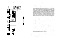
-1- SAFETY INSTRUCTIONS CONTENT SAFETY INSTRUCTIONS INTRODUCTION FRONT AND REAR PANEL INSTALLATION OPERATION UPS STATUS DISPLAY TROUBLE SHOOTING SERVICE BATTERY REPLACEMENT INPUT FUSE REPLACEMENT STORAGE AND PRESERVATION SOFTWARE INSTALLATION 1 4 10 16 19 21 27 30 31 33 34 34 Please read carefully and follow this ULTRA Series UPS guide. Important : Please keep this user's guide for reference in order to use the UPS properly and safety.
-2- 1.1.6 Do not touch any metal parts or any electrical connection when UPS is operating. 1.1.7 Use ONLY one hand when plugging and unpluging the load in order to avoid electric shock from touching two surfaces with different potential. 1.1.8 It is recommended to connect the UPS to a three wire AC source (two live wires and ground) which connects to a protected circuit such as employs a fuse or circuit breaker. -3- 1.3 Warning ! Battery Safety 1.3.
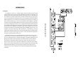
-4 - -5- INTRODUCTION The ULTRA Series UPS can be started when there is no power source. It is convenient for you to have spare power when the source fails or in an emergency. It also can communicate with a computer through the Easy-Mon X Monitoring and Management Software (sold separately) via USB or RS-232 (for some model) port . This software can monitor the UPS and AC source status on PC that connected directly to UPS. It allow user to schedule on-off the UPS, schedule self-test and data log.
-7- 2.2.2 Operating under backup mode -6- 2.2.1 Operating in the normal mode Normally, UPS is working under line interactive mode in which the path of current is as follows : When the current first flows into the UPS, it has to pass through a surge protection circuit to filter surges and spikes which may occur from a nearby lightning discharge or load switching by the local power company.
-8- 2.3 Features Advanced LEONICS Microprocessor control: A specially programmed microprocessor produced only for LEONICS is used as the CPU for the UPS. This makes the ULTRA Series UPS perform faster and more accurately to protect valuable equipment and its peripherals and provides advanced control features. Power Watcher: Full time load power monitoring and battery charge warnings are provided to make sure that your UPS will be able to properly backup power to the PC protected by UPS.
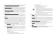
- 10 - - 11 - FRONT AND REAR PANEL 3.1 Front panel EASY DISPLAY LED DISPLAY LCD DISPLAY 3.1.1 Multi-function Switch: The switch to turn on, turn off, test the UPS and mute the audible alarm. For LED Display UPS, you can press it to change the display mode from input voltage - load level mode to battery voltage level mode and vice versa. 3.1.2 Utility Line OK / Fail (Lamp no. 1: green): Shows the utility power status. Lit : UPS is operating under its normal mode.
- 12 - 3.1.4 3.1.5 3.1.6 3.1.7 3.1.8 backup mode). Overload Alarm (Lamp no. 3: red): Shows load status. It will be lit when your connecting loads are exceeding the UPS capacity. Load Level: Shows how much power your loads are consuming compared to the UPS capacity from low to high level. 3.1.5.1 For the UPS with LED display (Lamp no. 4-7:green): Each lamp represents 25% of full load capacity and starts from Lamp no. 4 to 7. Please refer to section 6.2 The meaning of LED display. 3.1.5.
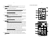
- 14 - 3.2.1 Surge protection for telephone line / LAN line (option): A port for fax / modem line surge protection. Its function is to protect load against voltage spikes coming from the telephone or LAN line (option). 3.2.2 No Load Shutdown Switch: Allows you to select whether the UPS will shutdown itself when power line fail if there is no load or not (no load are defined as all loads that connected to the UPS are less than 8 percent of UPS capacity). 3.2.
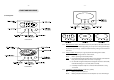
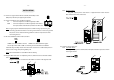
- 16 - INSTALLATION - 17 - 4.4.2 IEC type outlets Plug UPS output power cord which is supplied with the UPS into the UPS outlet and the inlet of the load. 4.1 Connect a signal cable from PC network (if available) to the USB port (or RS-232 port (option)) of the UPS. 4.2 Connect telephone line or LAN line (option). IN : Connect telephone or LAN line (option) to UPS. OUT : Connect telephone or LAN line (option) from UPS to the input socket of fax machine, modem or LAN card.
- 18 - - 19 - 4.5.2 IEC type outlets Get the input power cord from the load and plug into UPS AC input and wall receptacle as shown in the figure below. OPERATION 5.1 Switch on 5.1.1 Under normal utility power line (AC Start): Plug in the power cord to the electrical outlet. Press the multi-function switch for 0.5 second then release. All indicator lights will blink, after that UPS will start up the self-test (See details in section 5.3.1).
- 20 - 5.2 Switch off Under any operating conditions, there is only one proper way to shut off the UPS. Press the multi-function switch until the lamp no.1 ( ) and lamp no. 3 ( ) are lit at the same time and alarm sound once, then release. Note: If you press the multi-function switch too long (until the Utility line ok/fail ( ) and Overload alarm ( ) lamps are extinguished) and the second alarm beep sounds, the UPS will not switch off. 5.3 Self-test The ULTRA Series UPS has a self-test capability.
- 22 - - 23 - 6.1 Indicator lights No. 1, 2 and 3 Item UPS status 6.
- 24 - 6.2.3 Self-test display mode After the ULTRA Series UPS finishes a self-test, it will display : 6.2.3.1 A short beep and the one of Input Voltage Level lamps (no.4 -7) and Load Level lamps (no.8-11) will lit that means the UPS is normal. 6.2.3.2 A long beep indicates that the UPS has detected something abnormal. To mute the alarm, press the multi-function switch then observe the error from the display : - 25 - 6.3 The meaning of LCD display 6.3.
- 26 - - 27 - 6.3.3 Battery Level Display The third indicator is lit when software failure. The far-left bar is lit when battery level is very low. (Low Battery) The forth indicator is lit when CPU error. Two bars are lit when battery level is below 20%. The fifth indicator is lit when an inverter fault. Three bars are lit when battery level is from 21% to 40%. The top indicator is lit when battery power is too low. UPS will cancel the self-test automatically.
- 28 - Symptoms UPS operates normally but the lamp no.3 is blink or LCD display show over load sign on the top bar of load level display UPS operates normally but sounds a short beep periodically or UPS switches to backup power for a short period and returns to normal operating status. When a black out occurs, UPS supplies backup power but it is still supplying when the AC source recovers. Possible Causes - 29 - Solutions 4.
- 30 - Symptoms Possible Causes - 31 - BATTERY REPLACEMENT Solutions 3. If UPS can operate normally after you follow step 2, but this symptom always happens, please send the UPS to a LEONICS Service Center or LEONICS local distributor. When the UPS warns you to replace the battery (see details in item 6.2.3.2 and 6.3.4.2): Warning!: You can replace UPS’s battery while it is operating.
- 32 - - 33 - FUSE REPLACEMENT 9.3 Stand the UPS up, unscrew the screw on the battery strip. 9.4 Remove the battery terminal cover. Disconnect the black and red wires from the battery terminals. Then pull the battery out and replace with the new one. For the 1050VA or higher model, please notice each connection carefully before replace the new one. Caution!: 10.1 10.2 Turn off UPS. Unplug UPS input power cord, both from the UPS and the AC source. 10.
- 34 - STORAGE AND PRESERVATION If you have to store UPS for a long period of time, before storing, be sure the battery is fully charged and it need to be recharge every three months to preserve the condition of the Internal battery; 11.1 Plug the UPS power cord into an electrical outlet. 11.2 The indicator lights no. 2 blink at once. 11.3 Leave the UPS connected to the electrical outlet for at least 8 hours. 11.