Datacolor 650™ Datacolor 600™ Datacolor 400™ User’s Guide
Datacolor 650/600/400 User’s Guide Part No. 4230-0395M Rev 1, January, 2007 All efforts have been made to ensure the accuracy of the information presented in this format. However, should any errors be detected, Datacolor appreciates your efforts to notify us of these oversights. ©2007 Datacolor. Datacolor, SPECTRUM and other Datacolor product trademarks are the property of Datacolor. Microsoft and Windows are either registered trademarks of Microsoft Corporation in the United States and/or other countries.
Contents Datacolor Spectrophotometers ........................................................................ 1 About Datacolor Spectrophotometers..................................................................................1 Adjustable UV Filter Option ..........................................................................................2 Transmission Option (Datacolor 650/650V)..................................................................2 Vertical Mount Option (Datacolor 650V/600V/400V) ....
Sample Presentation and Measurement ........................................................ 33 Sample Presentation and Measurement Overview............................................................33 Reflectance Measurements ........................................................................................33 Sample Viewing Port ..................................................................................................34 Transmittance Measurements .............................................
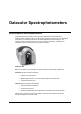
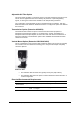
Datacolor Spectrophotometers About Datacolor Spectrophotometers The Datacolor high performance benchtop spectrophotometers (Datacolor 650™, Datacolor 600™, Datacolor 400™) are the newest generation of bench top color measuring instruments, incorporating state-of-the-art CMOS integrated circuit technology in the instrument design. All are intended for use as a device for measuring, specifying and evaluating color in both laboratory and production settings.
Adjustable UV Filter Option This option offers the ability to control the amount of UV light emitted from the light source. This is used for applications that need to identify the presence of optical brightening agents, or other types of fluorescent materials in the samples being evaluated. The configuration of the adjustable UV filter is handled through the software. See also Datacolor TOOLS user Guide for detailed instructions to configure the option and calibrate the instrument.
Safety Features If the equipment is used in a manner not specified by the manufacturer, the protection provided by the equipment may be impaired. CAUTION There are no user-serviceable parts for this equipment. Light Source Do not stare directly into the open port located in the front door panel when the measurement is in progress. Staring directly into the light source can result in eye discomfort similar to that of staring at a camera flash. Power CAUTION Disconnect power before servicing.
Accessories All models come with the following standard accessories: • Six foot power cable • Serial cable with connectors on either end • Black Trap • White Tile • Green Tile • USB Cable Calibration Tiles A black trap, white tile and green tile are provided with all instruments: • The black trap and white tile are used each time the instrument is calibrated. • The green tile is used to perform an optional diagnostic test.
Below are aperture plate specifications: Aperture Identification Sample Area Measured Sample Area Illuminated LAV 26mm 30mm MAV 16mm 20mm SAV 5mm 9mm USAV 2.5mm 6.5mm XUSAV 2.5mm 3.0mm NOTE The area illuminated is always 4mm greater than the diameter measured to reduce translucency errors. The exception to this is the XUSAV plate. Tips for Aperture Selection • Always use the largest possible aperture size.
Black Calibration Card Spectralon (White) Transmission Calibration Standard 6 • Accessories • Transmission Sample Holder Base. Datacolor 650 users must install this holder into the transmission chamber. For Datacolor 650V (vertical mount) units, the sample holder base is installed at the factory. • Transmission Sample Holders. Used to secure the transmission sample in the chamber. One is used for liquids and the other for solid samples.
Cable Installation Overview You must install a power cable, and either a USB cable or a serial cable to connect the instrument to a computer. NOTE Do not connect both cables to the unit. You have a choice of using either a serial cable or a USB cable, and both are provided with the instrument. The connections for the cables are found on the back of the instrument. WARNING Read the "Electrical and Environmental Requirements” section BEFORE connecting your instrument.
Serial Cable Installation You can connect the instrument to the computer using either a serial cable or a USB cable. Select one of them. This section provides instructions for using the serial cable. NOTE Do not connect both cables to the unit. The serial cable is shown below: 1. Connect the 9-pin male connector on the serial cable to the RS-232C female connector on the rear panel of the instrument. 2.
USB Cable Installation Instruments manufactured by Datacolor can now be connected to a USB port on a desktop system. See Appendix, System Requirements for USB Cable Installation before you attempt to connect to a USB port. You can connect the instrument to the computer using either a serial cable or a USB cable. Select one of them. This section provides instructions for using the USB cable. NOTES Do not connect both cables to the unit.
Driver Installation To prepare your computer and the Datacolor programs to communicate with your instrument using a USB port, you must install software files onto the computer. This is done by following a Wizard that will appear on your computer screen when you connect the USB cable to the instrument, and to the USB port on the back of the computer. 1. Place the USB Drivers and Documentation CD into the CD-Rom drive. 2. Connect the USB cable to both the instrument and the computer.
4. Continue to click the Finish button at the bottom of each window in the Wizard. The program will notify you that the procedure is completed. CAUTION Do not remove the USB Driver CD from the drive. The Wizard will close and then immediately reopen and then you will have to repeat the procedure a second time to successfully copy the file. 5. When you once again see the “Welcome” screen, click the Next button. 6. Repeat the steps mentioned above as you move through the Wizard again.
The COM port assignment is accessed through the Windows Control Panel as follows: 1. Click the Start button at the bottom left of the screen. The Start menu displays. 2. Place the cursor on Settings so that the program submenu displays, and click Control Panel. 3. When the Control Panel window displays, double-click on System. The Systems Properties dialog box displays.
4. Click the Hardware Tab.
5. Click the Device Manager button. The Device Manager window displays. 6. Go to the Ports heading. Click on the plus (+) to display the port selections. 7. Click USB Serial Port. The USB Serial Port (COM3) Properties dialog box displays.
8. Click Port Settings. The dialog box below displays: 9. Click the Advanced button. The Advanced Settings for COM3 dialog box displays. The field labeled COM Port Number displays the current assignment for the USB port. To change the port setting, click the drop-down list arrow. The list of COM ports is displayed. 10. Click on the port assignment to be used for the USB port. 11. When you have completed the changes, click OK.
NOTES 16 • USB Cable Installation Datacolor 650/600/400 User's Guide
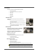
Controls and Indicators Controls and Indicators Panel On all benchtop models, a status panel is located on the top of the instrument. It identifies the current instrument settings being used. The indicators on the status panel vary, depending on the model of you are operating. Datacolor 600/650 The status panel is the same for the Datacolor 650 and 600. It is shown below: OPTION DESCRIPTION 420 The 420nm UV cutoff filter is selected.
OPTION DESCRIPTION UV Inc. No UV filter is selected. All UV wavelengths from the light source are included. UV Exc. The UV Excluded filter is selected. No UV wavelengths from the light source are included. Ready Instrument is ready for use. Spec Exc. The specular port is open and all measurements exclude the specular reflection from the sample. Spec Inc. The specular port is closed, and all measurements include the specular reflection from the sample.
3. Turn on the instrument power switch. This is located on the lower right side of your instrument toward the front. − When power is applied, all mechanisms are automatically reset. − The red lights on the status panel will flash briefly. NOTE If the instrument power is not turned on before a Datacolor program is launched, you may receive an error message. 4.
NOTES 20 • Powering Up Datacolor 650/600/400 User's Guide
Instrument Calibration Overview The instrument must be calibrated regularly to ensure that the measurements are accurate. This section provides instructions for performing both reflectance and transmittance calibrations. NOTE We recommend that you calibrate the instrument every 8 hours. Please refer to your software documentation for specific calibration instructions. Installing Calibration Data If this is a new instrument, you will need to install the calibration data.
2. When you complete the instrument configuration and select Save Setup, the program prompts you to place the diskette or CD containing the calibration data in the appropriate drive. When you do this, a screen similar to the one below will appear: 3. Two files should be displayed. If they are not, browse to the correct drive/folder location. 4. You must load both files. Highlight both file names, and click Open. The files will be transferred to the system.
Reflectance Calibration The instrument should be calibrated every 8 hours to compensate for changes in the environment. A black trap, white tile and green tile are provided with all instruments to complete the calibration: The black trap and white tile are used each time the instrument is calibrated. The green tile is used to perform an optional diagnostic test. Reflectance Calibration Procedure The software prompts for calibration vary from one program to another.
UV Filter Calibration The procedure for calibrating the adjustable UV filter is performed in reflectance mode, and requires the use of a fluorescent white tile, provided with the instrument. This procedure requires the selection of specific software options. See also the Datacolor Tools User’s Guide contains step-by-step instructions to calibrate the adjustable UV filter. NOTES This calibration procedure is critical to the accurate measurement, either reflectance or transmittance, of fluorescent samples.
Accessing the Transmission Compartment There are side-latch buttons on each side of the Datacolor 650 case that are used to open the transmission case: Button Front Back Depress these buttons, and slide the case toward the back of the instrument, to open the transmission compartment.
Transmission Accessories The following accessories must be installed in order to perform transmission measurements: Transmission Sample Holder Base. Installed by user. Transmission Sample Holders. Installed by user. Spill Tray. Installed at factory.
Transmission Sample Holder Base This base is installed by the user. It is used to mount the sample holder correctly in the chamber. Transmission Sample Holders Two sample holders are provided for transmission measurements. One is designed to hold a cuvette used for measuring liquids. The other is used for solid, transparent samples such as plastic plaques. Solid samples Cuvette Holder (liquid samples) NOTE The cuvette holder is designed to hold a cuvette 50mm X 10mm (Datacolor Part No. 29500004).
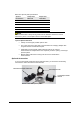
Spill Tray This tray is installed at the bottom of the transmission compartment, and is used to capture any overflow of liquid materials. Spill Tray Installing the Transmission Accessories Transmission Sample Holder Base The transmission sample holders are mounted on this base: The base attaches to a metal bar at the bottom of the transmission compartment. It is placed directly over the spill tray, and is secured through magnets.
Below is an example of the correct installation of the spill tray and sample holder base: Installed sample holder base Spill tray NOTES Exercise care when installing the base into the transmission compartment. The design is very tight. The spill tray is installed at the factory. Install the base in the transmission compartment before attaching either of the sample holders. No special tool is required for installation. The base must be removed to make closed-case reflectance measurements.
These sample holders are mounted onto the transmission sample holder base via two dowels protruding from the bottom of the holder. Dowel pins The base includes three positions to locate the sample between the sphere and the lens. The location of the sample holder along the base depends on the type of material being measured. Position 3. Places the sample close to the lens. It is used to measure regular transmission of transparent materials. Position 2.
Transmittance Calibration The following accessories are used to calibrate the instrument for transmittance: White Spectralon® Plaque. Typically placed at the sample port for calibration and measurement. Barium-coated MAV Aperture Plate Black Card. Used to “block” the lens during calibration. Calibration Procedure Before you begin, you should verify the current aperture selection. The setting must be Medium Area View (MAV) and the barium-coated MAV plate should be placed at the instrument port.
5. When the measurement is completed, remove the black card from the transmission compartment. 6. Place the white Spectralon® plaque at the sample port, and make the next measurement. NOTES The white plaque remains at the port for “Total” Transmittance measurements, and is replaced with the black trap for “Diffuse” Transmittance measurements. See also Sample Presentation and Measurement, Transmittance Measurements.
Sample Presentation and Measurement Sample Presentation and Measurement Overview You must pay close attention to the positioning of the sample to insure an accurate measurement. When positioned correctly, the sample rests between the sample holder and the front panel door. The sample must completely cover the aperture opening. Reflectance Measurements 1. Grasp the sample holder and pull forward. 2. Position the sample, then carefully bring arm back up to normal operating position.
Sample Viewing Port When measuring small samples, you may need to check that the sample is properly positioned at the port. To verify that the correct area of the sample is being measured: 1. Place the sample at the port. Grasp the black tab above the aperture plate. 2. Pull top of door down to its full horizontal position. 3. The backside of this door reveals the area of the sample covering the port opening.
4. Push the door back to its normal position. Transmittance Measurements Three techniques are used to measure the transmittance of samples: “regular” transmittance, “total” transmittance and “diffuse” transmittance. When working with samples that are completely transparent (such as dyes in solution or transparent plastics) you are measuring “regular” transmittance.
Sphere opening Front Back “Total” transmittance measurements are made with the white Spectralon® plaque in place. “Diffuse” transmittance measurements are made by replacing the Spectralon® plaque at the port with a light trap. Total Transmittance Diffuse Transmittance Consult with your Applications Specialist regarding the measurement technique you should use for specific evaluations.
Remote Measure Button The red button at the top of the instrument is used to start a measurement from the instrument, rather than from the program. NOTE The remote measure button is not available on all models. For those models equipped with it, it is active only when the software supports remote measurement.
NOTES 38 • Sample Presentation and Measurement Overview Datacolor 650/600/400 User's Guide
Maintenance About Instrument Maintenance The sections that follow provide detailed instructions for maintaining the instrument and calibration tiles. These instructions and tips will help to insure that the instrument continues to perform properly over its life. CAUTION There are no user-serviceable parts for this equipment. Sphere Cleaning The sphere should be examined visually for the presence of dust, sample particles, fibers, and excessive yellowing due to environmental influences.
4. Using the Minivac portable cleaning system, carefully vacuum away any loose materials in the sphere. WARNING Do not touch the inside of the sphere. The coating is very fragile. 5. When finished, replace the aperture plate. Tile Handling/Cleaning Handling Tiles • Handle calibration tiles with extreme care. Do not drop them, or scratch the glazed surface. • Always grasp the tile using its edges. Cleaning Tiles • The calibration tiles should be cleaned before each use.
Storage • Large temperature variations will affect the accuracy of your calibration, requiring more frequent calibration. The calibration tiles should be stored in an environment that simulates the temperature of the samples to be measured. • Prolonged exposure to sunlight or other sources of ultra-violet radiation will cause the color of the tiles to change. The tiles should always be stored in a protective case or container away from direct sunlight and environmental contaminants.
NOTES 42 • About Instrument Maintenance Datacolor 650/600/400 User's Guide
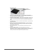
Appendix Optical Block Diagram The same optical configuration is used for the Datacolor 650, 600 and 400: Datacolor 650/600/400 User's Guide Optical Block Diagram • 43
Datacolor 650/600/400 Instrument Specifications Specifications are subject to change without notice. ITEM DESCRIPTION Instrument Type Dual beam integrating sphere with xenon flash lamp. Measuring Geometry Diffuse illumination, 8º viewing in conformance with CIE publication No. 15.2 Colorimetry. Illumination Source Pulsed xenon, filtered to approximate D65. Sphere Diameter 152 mm / 6.
Features by Model FEATURE 650 600 400 Reporting Interval 5 or 10nm** 5 or 10nm** 10nm Effective Bandwidth 5 or 10nm** 5 or 10nm** 10nm 20 Read Repeatability on White Tile Using Dual Flash (CIELAB) 0.015 (max) 0.015 (max) 0.035 (max) Inter-instrument Agreement— Reflectance Measurements* (CIEL*a*b*) 0.15 (max) 0.08 (avg) 0.15 (max) 0.08 (avg) 0.30 (max) 0.15 (avg) Transmittance Measurements Yes*** No No Inter-instrument Agreement for Regular Transmittance (550 nm)* ±0.
Dimension Comparison - Horizontal vs. Vertical Mount The Datacolor 600 V and Datacolor 400 V are vertically mounted, with the sample port facing down. This provides the option to present the sample to the instrument vertically. These models conform to all specifications for the Datacolor 600™ and Datacolor 400™, with the exception of the dimensions.
Miscellaneous Technical Information System Requirements for USB Connection Below are the software and firmware versions required to successfully connect a Datacolor instrument to a USB port. Operating Systems Windows 2000, Windows XP Pro USB Firmware 1.1 or higher RS-232C Connector Pin Assignments Pin # Purpose Direction 2 Transmit data Out (to host) 3 Receive data In (from host) 7 Signal ground CAUTION (1) DO NOT WIRE to pins other than 2, 3, and 7.
Canadian Compliance Statement English This digital apparatus does not exceed the Class A limits for radio noise emissions from digital apparatus set out in the Radio Interference Regulations of the Canadian Department of Communications. Francais El present appareil numerique n’emet pas de bruits radioelectriques depassant les limites applicables aux appareils numeriques de la class A prescrites dans le Reglement sur le brouillage radioelectrique edicte par le ministere des Communications du Canada.
Index 2 20 Read Repeatability on White Tile Using Dual Flash (CIELAB), 45 G Green Tile, 4 H A Horizontal Mount, 46 Absolute Operating Environment, 44 Accessories, 4 Adjustable UV Filter Option, 2 Aperture configuration, 44 detection, 45 opening, 33 plates, 4, 45 B Black Trap, 4 cleaning, 41 C Cable installation, 7 power, 7 USB, 9 COM Port Assignment, 15 Compliance Statements, 47 Controls, 17 D Dimension Comparison, 46 Dimensions, 44 E Effective Bandwidth, 3 F Feature Summary, 3 Features by Model, 45
P Photometric Range, 44 Power, 44 cable, 4 Powering Up, 18 R Reflectance calibration, 23 measurements, 33 Remote Measurement Button, 37, 45 Reporting Interval, 45 Requirements - electrical/environmental, 2 RS-232C Connector Pin Assignments, 47 S Sample Measurement, 33 Sample Presentation, 33 Sample Viewing Port, 34 Serial Cable, 4 SP2000 Spectral Analyzer, 3 Spectral Analyzer, 44 Spectralon® Plaque, 41 Spectrophotometers, 1 Specular Port, 44 Sphere Cleaning, 39 System Port Assignment, 11 T calibration,