TM WE GET PEOPLE FLYING ™ TM E .40-SIZ N VERSIO INSTRUCTION MANUAL • 90% prebuilt • Hardware included • Precovered trim scheme • Everything included to build the conventional two-aileron wing version or quad flap version Specifications: Wingspan:. . . . . . . . . . . . . . . . . . . . . . . . . . . . . . . . . . . . 573/4" Length: . . . . . . . . . . . . . . . . . . . . . . . . . . . . . . . . . . . . . . . 51" Wing Area: Standard: . . . . . . . . . . . . . . . . . . . . . . . 700 sq in Quad Flap: . .
Table of Contents Introduction . . . . . . . . . . . . . . . . . . . . . . . . . . . . . . . . . . . . . . . . . . . . . . . . . . . . . . . . . . . . . . . . . . . . . . . . . . . . . . . . . . . . . . . . 3 Warning . . . . . . . . . . . . . . . . . . . . . . . . . . . . . . . . . . . . . . . . . . . . . . . . . . . . . . . . . . . . . . . . . . . . . . . . . . . . . . . . . . . . . . . . . . . 3 Additional Required Equipment . . . . . . . . . . . . . . . . . . . . . . . . . . . . . . . . . . . . . . . . .
Introduction Important Before beginning construction of your Ultra Stick™ 40, decide which wing configuration is best for you—the conventional two-aileron version or the quad flap version with two ailerons and two flaps. With the conventional two-aileron wing, the Ultra Stick 40 is an outstanding sport aircraft. This configuration offers excellent slow speed and stall characteristics that allow even inexperienced pilots to feel at home.
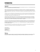
Additional Required Equipment Radio Equipment 4 channels (minimum) 5 servos (JR 527 or equivalent) or 7 servos for quad flap wing option Standard 600–1100mAh receiver battery pack Note: A Y-harness and a reversed servo is required if a 5- or 6-channel radio is used for quad flaps. A servo Y-harness with reverse, like Expert’s 320 (EXRA320), can be used. Recommended JR Systems JR F421EX JR XP631 JR XP652 JR XP8103 PCM10X PCM10Sx PCM10SxII Engine Requirements .40 - .58 2-cycle engines .50 - .
Parts Needed (not included in kit) Aileron Extension - 12" (2) (JRPA100) (4 aileron extensions required for the quad flap wing option) Propeller (Refer to propeller recommendations for the operating instructions of your engine) Foam for cushioning tank Fuel tubing - 12" Tools and Supplies Needed (not included in kit) Adhesives Thin CA (cyanoacrylate) glue Medium CA (cyanoacrylate) glue Thick CA (cyanoacrylate) glue CA remover/debonder 6-minute epoxy 30-minute epoxy Threadlock Z-42 Masking tape Tools Drill
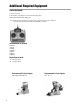
Kit Contents Large Parts 1. Left Wing Panel w/Aileron (HAN1677) 2. Right Wing Panel w/Aileron (HAN1677) 3. Fuselage (HAN1676) 4. Horizontal Stabilizer and Elevator (HAN1678) 5. Vertical Stabilizer and Rudder (HAN1678) 6. Optional Flap/Aileron Parts (for quad flap wing, included) (HAN1679) 3 2 1 6 5 4 Note: Photo of product may vary slightly from contents in box.
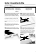
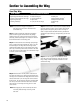
Section 1: Assembling the Wing Conventional Aileron Parts Needed • Right wing panel with aileron and hinges • Left wing panel with aileron and hinges Tools and Adhesives Needed • Instant thin CA glue • CA remover/debonder • Paper towels • T-pins (one for each hinge) • Sealing iron Before construction begins, decide what style of wing is desired (conventional or quad flap) and what type of engine will be mounted on the model. The conventional aileron wing will be presented in this section.
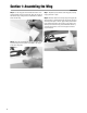
Section 1: Assembling the Wing CONTINUED Step 5. Turn the wing panel over and deflect the aileron in the opposite direction from the opposite side. Apply thin CA glue to each aileron hinge, making sure the CA penetrates into both the aileron and the wing. Step 6. Using CA remover/debonder and a paper towel, remove any excess CA glue that may have accumulated on the wing or in the aileron hinge area. 8 Step 7. Repeat this process with the other wing panel, securely hinging the aileron in place. Step 8.
Section 1: Assembling the Wing CONTINUED Sealing the Hinge Gaps Although not mandatory, it is always a good practice to seal the hinge gap of the aileron control surfaces. Sealing the hinge line has several advantages. A sealed hinge line gives a greater control response for a given control deflection. It also offers more precise, consistent control response and makes trimming the aircraft during flight easier. Step 11.
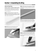
Section 1a: Assembling the Wing Quad Flap Wing Parts Needed • Right wing panel with aileron and hinges • Left wing panel with aileron and hinges • Right wing aileron/flap • Left wing aileron/flap Tools and Adhesives Needed • Instant thin CA glue • CA remover/debonder • Paper towels • T-pins (one for each hinge) Note: The procedure for hinging the flap/aileron in each wing panel is the same as described for the conventional wing. Step 1a.
Section 1a: Assembling the Wing CONTINUED Step 6a. Using CA remover/debonder and a paper towel, remove any excess CA glue that may have accumulated on the wing or the aileron. Step 7a. Repeat Steps 4a through 6a for the flap control surface. Step 10a. To seal the aileron and flap hinge line, cut a piece of White UltraCote® (GBG870, not included) approximately 3" wide to the length of each hinge line.
Section 1a: Assembling the Wing CONTINUED Step 12a. With the piece of covering still folded, use a hobby knife with a sharp #11 blade and a straight edge to carefully cut the entire length of the covering at the marks you made in the previous step. Step 13a. Remove the backing from the covering. Place the folded crease into the center of the hinge line on the bottom of the wing. Using a straight edge, hold one side of the covering in place while ironing down the opposite side with a sealing iron.
Section 2: Joining the Wing Halves Parts Needed • Right/left wing panels • Plastic wing bags (optional) • Wing joiner brace Tools and Adhesives Needed • 30-minute epoxy • Epoxy brush • Mixing stick • T-pin • Masking tape • Hobby knife Step 1. Locate the wing joiner. Using a ruler, determine the center of the brace and mark it with a pencil. • Rubbing alcohol • Paper towels • Wax paper • Ruler • Pencil Step 4. Separate the wing halves and remove the wing joiner.
Section 2: Joining the Wing Halves Step 6. Place one wing half right-side-up on a flat work surface. CONTINUED Step 8. Apply a generous amount of epoxy into the wing joiner cavity of the other wing panel. Note: Use wax paper underneath the wing center while the epoxy is curing. With the wing lying flat on a surface without any dihedral, apply more masking tape to the wing center joint and recheck that the wing remains flat. Also make sure the wing halves are properly aligned.
Section 3: Installing the Aileron/Flap Servos Parts Needed Tools and Adhesives Needed • Assembled wing • Standard servos with mounting hardware (2) (4 for quad/flap configuration) Note: The flap servo must be reversed if using a Y-harness for flaps • Servo extension -12" (2) (4 for quad-flap configuration wing) • Hobby knife • Medium Phillips screwdriver • Drill • Drill Bit: 1/16" • Masking tape • Pencil • String with weight on end • Needle-nose pliers Step 1.
Section 3: Installing Aileron/Flap Servos CONTINUED Step 7. Before mounting the servos in the wing, it’s suggested the servo extensions be run through the wing and out the opening near the root rib. Step 11. Tape the lead to the wing to keep it from falling back into the opening. It may be easier if you thread one servo lead at a time. Step 8. Locate the two servo lead exits (oval-shaped) near the center of the wing bottom.
Section 4: Bolting the Wing to the Fuselage Parts Needed • Fuselage • Wing • Leading edge wing dowels • Wing-bolt plate • Wing bolts Tools and Adhesives Needed • Drill • Drill Bit: 1/4" • Hobby knife • Round file • Flat screwdriver Note: Your Hangar 9™ Ultra Stick™ 40 comes from the factory with two predrilled holes in the leading edge of the wing for the alignment dowels. You will have to drill out the two bolt holes in the trailing edge of the wing.
Section 4: Bolting the Wing to the Fuselage Step 5. With the wing centered check the alignment by measuring from each wing tip to the rear of the fuselage. Be sure to use the same point on each wing tip exactly the same distance on each side from the center of the wing. Refer to the figure below. Step 6. With the wing centered and aligned to the fuselage, mark the wing exactly in line with the sides of the fuselage. Step 7. Remove the wing from the fuselage.
Section 4: Bolting the Wing to the Fuselage CONTINUED Step 11. Using a 1/4" drill bit, carefully drill through the wing at the indents in the bottom of the wing. Be careful when the drill bit exits the top of the wing that you do not tear the covering. Note: When you drill the wing bolt holes, be sure to drill the holes perpendicular to the top surface of the wing. Step 12. After you have drilled the wing for the wing bolts, trial fit the wing into position on the fuselage.
Section 4: Bolting the Wing to the Fuselage CONTINUED Step 15. Install the wing back onto the fuselage and gently snug the wing bolts, securing the wing to the fuselage. Mark the wing bolt plate location on top of the wing. Remove the wing bolts and plate from the wing. Step 16. Using a hobby knife, carefully trim away the covering on the wing just inside the lines you marked for the wing bolt plate. Be sure to avoid cutting into the balsa wood. 20 Step 17.
Section 5: Installing the Horizontal Stabilizer Parts Needed • Horizontal stabilizer • Fuselage • Assembled wing Tools and Adhesives Needed • Hobby knife • Ruler • Felt-tipped pen • Pencil • 30-minute epoxy Note: Before assembling the tail, be sure the elevator and the CA hinges are removed from the horizontal stabilizer. The hinges and elevator will be installed later. Step 1. Measure and mark the center of the horizontal stabilizer at its leading and trailing edges. Step 2.
Section 5: Installing the Horizontal Stabilizer CONTINUED Step 8. With the fuselage and horizontal stabilizer together on a flat surface, check to be sure the wing and horizontal stabilizer are parallel with each other. If adjustment to the horizontal stabilizer saddle is necessary because the wing and stabilizer are not parallel, carefully sand the horizontal stabilizer saddle to adjust as necessary.
Section 6: Installing the Vertical Stabilizer (Fin) Parts Needed • Vertical stabilizer with rudder • Fuselage Tools and Adhesives Needed • 30-minute epoxy • Hobby knife • Pencil • Masking tape • Rubbing alcohol Step 1. On the rear of the fuselage, a slot is precut in the wood structure for the vertical stabilizer. Using a sharp hobby knife cut away the covering on the top rear of the fuselage where the vertical stabilizer inserts into the fuselage. Step 2.
Section 6: Installing the Vertical Stabilizer (Fin) CONTINUED Step 6. Mix approximately 1/4 ounce (minimum) of 30-minute epoxy and apply it to the vertical stabilizer where it comes into contact with the fuselage. Also apply epoxy to the base of the vertical stabilizer where it comes in contact with the horizontal stabilizer. Important: It is essential that the vertical stabilizer base be epoxied to the horizontal stabilizer inside the fuselage to provide adequate strength. Be sure to use plenty of epoxy.
Section 7: Installing the Rudder and Tail Wheel Assembly Parts Needed • Fuselage • Rudder • Hinges • Tail wheel assembly • Tail wheel • Tail wheel collar Tools and Adhesives Needed • Drill • Drill Bits: 3/32 ", 1/16 " • Hobby knife • Felt-tipped pen • Toothpicks (optional) • Thin CA glue • CA remover/debonder Step 1. Trial fit the rudder in position on the vertical stabilizer.
Section 7: Installing the Rudder and Tail Wheel Assembly CONTINUED Step 5. Using a hobby knife, cut a slot or groove into the back of the fuselage as marked to accept the tail wheel pivot bushing in Step 3. Note: When you attach the elevator, you’ll have to cut a small groove so the bushing clears the elevator. Step 6. Trial fit the tail wheel assembly and rudder in place. Deflect the rudder, making sure the tail wheel assembly turns freely with the rudder. Step 7.
Section 7: Installing the Rudder and Tail Wheel Assembly CONTINUED Step 9. Mix approximately 1/4 ounce of 30-minute epoxy and apply it to both the pivot bushing where it goes into the fuselage and into the hole in the rudder you drilled in Step 4. Hint: A toothpick applicator may be helpful in getting the epoxy into the holes. Step 13. Work the rudder left and right to make sure the movement is free and that the tail wheel assembly tracks accordingly. Step 14.
Section 8: Hinging the Horizontal Stabilizer and Elevator Parts Needed • Fuselage • Elevator • CA hinge Tools and Adhesives Needed • Thin CA glue • CA remover/debonder • Paper towels • White Goldberg UltraCote® Step 1. Locate the elevator and CA hinges. Hinge the elevator in the proper position on the horizontal stabilizer using the same hinging technique used in Section 1. Remember to remove the T-pins before applying the CA glue. Also, make sure the tail wheel is free to move its full range.
Section 8: Hinging the Horizontal Stabilizer and Elevator CONTINUED Step 6. Measure 3/8" for the folded crease out. Make several marks along the length of the folded covering. Step 8. Remove the backing from the covering. Place the folded crease into the center of the hinge line on the bottom of the horizontal stabilizer. Using a straight edge, hold one side of the covering in place while ironing down the opposite side with a sealing iron. Step 7.
Section 9: Installing the Rudder and Elevator Control Horns Parts Needed • Control horns (2) • Control horn backplates (2) • Control horn screws (6) • Fuselage Important: When installing the control horns, it’s important that the holes in the control horns where the pushrod attaches are directly in line with the control surface hinge line. Step 1. To locate the elevator control horn position, measure over 5/8" on the right side of the horizontal stabilizer along the fuselage.
Section 9: Installing the Rudder and Elevator Control Horns CONTINUED Step 5. Measure 3/4" from the top of the fuselage on the left side of the rudder. Mark the location with a felt-tipped pen or pencil. This mark will serve as the center for the rudder control horn. Step 7. Drill these holes with a 1/16" drill bit and install the rudder control horn using the screws and backplate provided. Note: Be sure that this will place the horn so the screws are on either side of the tail wheel wire in the rudder.
Section 10: Installing the Main Landing Gear Parts Needed • Main landing gear • Fuselage • Landing gear axles with lock nuts(2) Tools and Adhesives Needed • Wheel collar with screw (2) • Wheels, 21/2" (2) • Landing gear bolts (2) Step 1. Attach the axles to the aluminum landing gear using the lock nuts provided. Slide on the wheel. Use the wheel collar to hold the wheel on the axle. • Phillips screwdriver • Moto-tool with cut-off wheel • Threadlock Step 2.
Section 11: Assembling the Fuel Tank Parts Needed Tools and Adhesives Needed • Metal tubes (2) • Clunk (fuel pickup) • Fuel pickup tubing • Fuel tank • Metal caps (2) • Rubber stopper • 3 mm screw • Hobby knife • Medium screwdriver • Drill Bit: 1/16" Step 1. Locate the tank parts. Step 3. Slide the smaller of the two caps over the tubes on the smaller end of the rubber stopper. The small end will be inserted into the fuel tank.
Section 11: Assembling the Fuel Tank CONTINUED Step 5. You will need to make a bend in one of the tubes to bend up inside to the top of the tank when the cap assembly is installed onto the fuel tank. Insert the cap assemble to the tank and see if the tube is near the top of the tank as shown below. If not, remove the cap assembly and bend tube until it reaches the top of the tank, but not touching it. Be careful not to "kink" the tube when bending. Top Step 7.
Section 12: Installing the Throttle Pushrod Tube, Engine Mount, Engine, and Fuel Tank Parts Needed Tools and Adhesives Needed • Fuselage • Hangar 9™ Universal .40-size Engine Mount w/Hardware • Engine • Assembled fuel tank • Protective foam (not included) • Throttle pushrod tube • CA glue • Phillips Screwdriver or Hex wrench • Threadlock • 30-minute exopy The firewall is fuel-proofed at the factory.
Section 12: Installing the Throttle Pushrod Tube, Engine Mount, Engine, and Fuel Tank CONTINUED Step 4. The Hangar 9 Engine mount fits nearly all .40–58 two-stroke engines and .50–72 four-stroke engines. Trial fit your engine into the engine mount. ™ Step 5.
Section 12: Installing the Throttle Pushrod Tube, Engine Mount, Engine, and Fuel Tank CONTINUED Step 9. After you have the engine mount and fuel tank installed, turn the fuselage on its left side. Install your engine in between the engine beams and install the metal clamps and four bolts and nuts to hold the engine in place. Center the engine on the engine mount beams between the clamping bolts and tighten. Be sure the nuts are captured in the bottom of the engine mount. Step 10.
Section 13: Installing the Radio System Parts Needed • Radio system with 5-7 servos and hardware (not included) • Fuselage • Radio packing foam (not included) • Antenna tube (optional, not included) • Y-harness (optional—must have if using 4-channel radio) • Medium Phillips screwdriver • Hobby knife • Drill • Drill Bit: 1/16" Step 1. Install the rubber grommets and eyelets in three servos. Position the servos in the fuselage servo tray as shown, noting the location of the servo horns.
Section 13: Installing the Radio System CONTINUED Step 4. Wrap the receiver battery in foam and place it in the fuselage area forward of the servo tray and receiver. We suggest using layers of foam to hold the battery. Using a sharp hobby knife, cut a solid layer of foam the size of the compartment area that is in front of the servo tray. Cut another layer of foam that is identical in size with an opening in the center that is the size of the battery pack.
Section 14: Installing the Aileron and/or Quad Flap Linkages Parts Needed Tools and Adhesives Needed • Wing assembly w/servos installed • Short rods, threaded on one end (2 for conventional wing, 4 for quad flaps) • Clevis (2 for conventional aileron, 4 for quad flaps) • Wire keepers (2 for conventional aileron, 4 for quad flaps) • Control horn (2 for conventional wing, 4 for quad flaps) • Control horn mounting screws • Clevis keepers (4 for conventional wing, 8 for quad flaps) • Medium Phillips screwdri
Section 14: Installing the Aileron and/or Quad Flap Linkages CONTINUED Step 3. The control horn should be positioned so the holes that the clevis connects onto are over the centerline of the hinge line of the control surface. Step 6. Thread a 2-56 clevis on the end of one of the threaded rods. Screw the clevis on 7-10 turns. Install the clevis with wire on the control horn into the third hole from the mounting base. Be sure to install the clevis keeper over the clevis.
Section 14: Installing the Aileron and/or Quad Flap Linkages CONTINUED Step 9. Remove the clevis from the control horn. Attach a wire keeper to the end of the rod with the 90-degree bend. Step 10. Insert the 90-degree bend through the second hole from the end of the servo arm and install the end of the wire keeper over the end of the wire. Install the clevis back onto the control horn. Be sure to slide on the silicon clevis keeper onto the end of the clevis. 42 Step 11.
Section 15: Installing the Rudder, Elevator, and Throttle Pushrods Parts Needed Tools and Adhesives Needed • Fuselage • 30" pushrod wire, 2-56 threaded on one end (2) • 16" pushrod wire, 1.5mm (throttle) • Control horn (2) • Wire keeper (2) • Clevis (2) • Easy connector • Clevis keeper (2) • Felt-tipped pen/pencil • Hobby knife • Needle-nose pliers Step 1. Locate one of the long 30" pushrod wires threaded on one end, a 2-56 clevis, wire keeper, control horn, and mounting hardware and a clevis keeper.
Section 15: Installing the Rudder, Elevator, and Throttle Pushrods CONTINUED Step 5. Remove the clevis and slide the pushrod wire out of the guide tube. Make a 90-degree bend in the rod at the location you just marked and cut off the rod leaving 1/4" extend out from the 90-degree bend. Step 8. Repeat the process for either the rudder or elevator, whichever one you have not done.
Section 15: Installing the Rudder, Elevator, and Throttle Pushrods CONTINUED Step 11. Install the easy connector to the throttle servo arm by inserting the bottom post through the second hole from the end in the servo arm. Install the snap washer on the easy connector stem securing it to the servo arm. Step 14.
Section 16: Control Throw Recommendations The following control throw recommendations offer positive response when using the aileron-only configuration and are a good place to begin setting up the aircraft. After you have become more familiar with the flight characteristics of the Ultra Stick 40, adjust the control throws to meet your flying style.
Section 18: Quad Flaps The quad flap option allows your Ultra Stick™ 40 to perform in ways that are just not possible with the conventional aileronsonly setup. With the quad flaps and a computer radio, different wing configurations can be programmed to extend the flight performance envelope. Plus, it’s a great way to learn more about your computer radio. Some of these configurations include: Crow Dive Brakes to Landing On your first attempts to do the Harrier, start high.
Section 18: Quad Flaps What does elevator-to-flap do? Elevator-to-flap mixing causes more aggressive pitching when elevator is applied, making for tighter inside and outside loops. Using the recommended throws, the Ultra Stick™ 40 is capable of very tight 15-foot diameter loops. First flight profile It’s a good idea to start up high then turn on the elevator-to-flap mixing to get accustomed to the increased pitch (elevator) sensitivity.
Section 19: Programming Guide Following is a programming guide that provides step-by-step illustrations on how to program quad flap configurations for JR’s XP652/642, XP783/347/388S, XP8103, and 10X/10SxII/10Sx radios, as well as for Futaba’s 8-channel 8UA/S radio. Once you understand your computer radio, you’ll soon discover that there are many other possible programming configurations (e.g., right rudder causes the right aileron to go up and the right flap to go down, causing a severe right yaw).
Section 19: Programming Guide — JR XP652/642 CONTINUED RST INDICATES DATA RESET FUNCTION AC MODEL TYPE TO RESET + ENTER MODE CHANNEL INCREASE Press the MODE button until “RST” appears on the screen. + ENTER CLEAR INCREASE CHANNEL Press the mode button to access the mix wing screen. until “RST” appears on your screen. Now press the Increase and Decrease keys simultaneously to reset the programming to factory defaults.
Section 19: Programming Guide — JR XP652/642 CONTINUED INDICATES THE SUB - TRIM FUNCTION THR SB-TRIM 0 CHANNEL 1 2 3 4 5 6 THR : THROTTLE AIL : AILERON ELE : ELEVATOR RUD : RUDDER GER : LANDING GEAR FLP : FLAP (AC ONLY) SUB - TRIM VALUE (±125) + ENTER MODE CHANNEL Press the MODE button until “SB -TRIM” appears on the screen. Press the CHANNEL button until the desired channel appears on the screen. Step 4.
Section 19: Programming Guide — JR XP652/642 CONTINUED INDICATES THE DUAL RATE FUNCTION Note: The dual rate switch position is changed/accessed by setting the appropriate dual rate switch to the 0 or 1 positions. CHANNEL AI : AILERON EL : ELEVATOR AIO D/R I00% SWITCH POSITION (0 OR 1) DUAL RATE VALUE (0–125%) + ENTER MODE CHANNEL Press the MODE button until “D/R” appears on the screen. Press the CHANNEL button until “AI” or “EL” appears on the screen. Step 6.
Section 19: Programming Guide — JR XP652/642 CONTINUED CURRENT MIX + ENTER MODE CHANNEL – CLEAR INCREASE DECREASE MIX A35 % 35 Press the MODE button until “MIXALL” appears on the screen. Step 8. Mixing elevator-to-flaps: Press the Mode key until the “MIX A11” screen appears. This is programmable MIX A and it allows you to mix any channel to any other channel or even to itself. Press the Channel key until the “MIX Ach” appears.
Section 19: Programming Guide — JR XP652/642 CONTINUED Takeoff Flap Switch Crow Switch Elevator-to-flap mix can be assigned to one of these switches or always left on. Note: The takeoff flaps should be retracted before using the Crow function to prevent any over-travel of the flap servos.
Section 19: Programming Guide — JR XP783/XP347/XP388S Programming Your JR XP783, XP347 and XP388S in 14 Easy Steps JR’s XP783, XP347 and XP388S all feature the same base level programming, so the procedure for setting up quad flaps for each radio is identical. Note: Most of the quad flap features needed for the Ultra Stick are already preprogrammed in the glider (referred to as GLID) software included in these three radios.
Section 19: Programming Guide — JR XP783/XP347/XP388S CONTINUED TYPE Function Being Programmed UP GLID Select Aircraft Type HELI : Helicopter ACRO : Airplane GLID : Glider DN + CH – CLR Select Aircraft Type Step 2. Selecting model type (GLID): In System Setup mode, press the Up key until the “TYPE” screen appears. MIX V–TL Wing Type Display V-TL : V-Tail DUA-F : Dual Flap UP DN + CH Step 3.
Section 19: Programming Guide — JR XP783/XP347/XP388S CONTINUED AILE : Aileron (Right Aileron) ELEV : Elevator SPOI: Throttle RUDD : Rudder AILE: Aileron (Left (Right Aileron Aileron – Aileron1)1) GEAR : Gear ELEV: Elevator1 AUX1 : Auxiliary Flap Channel for Dual Flaps) AIL2: (Right Left Aileron AUX2 : Auxiliary 2 FLAP: Right Flap (Left Flap Channel for Dual Flaps) AUX2: Left Flap Function Being Programmed REVERSE SW RUDD NORM Channel Display UP DN Setting Condition NORM : Normal REV : Reverse CH
Section 19: Programming Guide — JR XP783/XP347/XP388S CONTINUED THRO: AILE1: ELEV: RUDD: AIL2: FLAP: AUX2: Throttle (Spoiler) Aileron (Right Aileron) AILE : Aileron (Right Aileron) Elevator ELEV : Elevator Rudder RUDD : Rudder Gear (Left Aileron – Aileron 1) – Aileron 1) : Gear (Left Aileron GEAR : Auxiliary 1 AuxiliaryAUX1 1 (Right Flap Channel (Right Flap Channel for Dual Flaps)for Dual Flaps) : Auxiliary 2 AuxiliaryAUX2 2 (Left Flap Channel for Dual Flaps) (Left Flap Channel for Dual Flaps) Sub-Trim Va
Section 19: Programming Guide — JR XP783/XP347/XP388S CONTINUED Indicates Channel for Which Dual Rate Function is Being Programmed 100 AIL.0 DUAL-RATE Function Being Programmed AI L : Aileron ELE : Elevator RUD : Rudder % POS Dual Rate Value 0 – 125% Dual Rate Switch Position Being Adjusted 0 or 1. Select with D/R switch UP DN + CH Increase or Decrease Dual Rate Value Channel Selection Step 9. Adjusting the dual rates: Press the Up key until the “DUAL-RATE” screen appears.
Section 19: Programming Guide — JR XP783/XP347/XP388S CONTINUED This may show up as E-F.D unless you hold up elevator. Position Indicator 0 POS MIX E-F.U Function Being Programmed UP DN Elevator Operating Direction D : Down Elevator U : Up Elevator CH To E-F Activation Switch Selection Step 11. Mixing elevator to flap: With the flap switch in the upper position, press the Up key until “MIX E-F.U” appears on your screen. This is the elevator-to-flap mix.
Section 19: Programming Guide — JR XP783/XP347/XP388S CONTINUED Step 13: Setting up Crow: Crow will be assigned to the flap switch and will be activated when the switch is in the down position. We’ve already set the flaps to the proper down position in MIX Step 7 travel adjust. Now we need to add the ailerons up 3/4" and the elevator down 5/8".
Section 19: Programming Guide — JR XP783/XP347/XP388S CONTINUED Flap Switch UP = Normal MID = Takeoff flaps DOWN = Crow 62 Mix Switch = Turns on/off aileron-to-flaps and elevator-toflaps mixes
Section 19: Programming Guide — JJR XP8103 Programming JR’s XP8103 in 14 Easy Steps Note: Most of the quad flap features needed for the Ultra Stick are already preprogrammed in the glider (referred to as GLID) software included in the XP8103. While the Ultra Stick™ 40 is not a glider, there are several built-in features in the glider programming that make quad flap easier to program and use. We strongly suggest using the GLID model type programming that’s included in these radios.
Section 19: Programming Guide — JJR XP8103 CONTINUED Note: When setting up a new aircraft, it’s important to reset the programming to the factory defaults. Model number to be reset UP SELECT DN CH CH CLEAR Press to return to factory preset data. Step 1. Resetting the programming to factory defaults: Hold down both the Up and the Down keys and turn on the radio to enter System Setup mode. Now press the Up key three times to move the cursor to the “MDL Reset” menu (Model Reset).
Section 19: Programming Guide — JJR XP8103 CONTINUED Current Flap Channel Input Pot 6: Flap Knob FLP.SW+PG: Flap Switch and Pot 6 UP DN SELECT CH CH CLEAR Press either the (+) or (-) key to select Pot 6 or FLP.SW +P6. Step 4. Assigning the flaps to the flap switch: In System Setup Mode press the Up key until “Input Sel.” (Flap Input) Press to reset Flap input to Pot 6. appears on the screen. Press the (+) key so that “FLP.SW+P6” appears in the lower screen.
Section 19: Programming Guide — JJR XP8103 CONTINUED Setting Operation →Channel→INH Trim Display Pot 5: Flaperon Flap Trim Pot 6: Dual Flap-Flap Trim Pot 7: Aileron Trim of Dual Flap UP DN Each Trim’s Operational Direction SELECT CH CH Press either CH key to select the desired trim POT. →POT 5 ↓ POT 6 ↓ POT 7 Step 6. Turning off the trim knobs: In Function mode, press the Up key until the “D/FLAP T”. (dual flap trim) screen appears.
Section 19: Programming Guide — JJR XP8103 CONTINUED Channel Being Programmed SPOI Throttle AIL1 Aileron Right ELEV Elevator RUDD Rudder AIL2 Left Aileron FLAP Flap (Right) AUX2 Flap (Left) UP DN SELECT Press to display channels 1-4 and 5-8 (2 screens). CH CH Channel Selection CLEAR Press to increase or decrease travel value; move stick or switch to manipulate arrow to the position to be adjusted (high/low, left/right). Step 8. Setting travel adjust: Press the Up key until the “TRVL ADJ.
Section 19: Programming Guide — JJR XP8103 CONTINUED “SW OFF” appears when the flap mixing is in the middle of lower position Elevator Operating Direction (D=Down, U=Up) Elevator to Flap Mixing Value (Range ± 125%) Indicates current mixing switch activated: Indicates the function selected ↓ Rate ↓ SW UP DN ON: Always ON MIX: Mixing Switch FLP (-) D: ON when Flap Switchs in lower position FLP (-) U: ON when Flap Switchs in upper position SELECT CH CH Press either CH key to select function: ↓ Rate ↓
Section 19: Programming Guide — JJR XP8103 CONTINUED Step 12. Setting up Crow: Crow will be assigned to the flap switch and will be activated when the switch is in the down position. We’ve already set the flaps to the proper down position in Step 8 travel adjust. Now we need to add the ailerons up 3/4" and the elevator down 5/8". “SW OFF” appears when the flap mixing is in the middle or upper position. Indicates the function being selected: Flap to Aileron Mixing Value (± 125%).
Section 19: Programming Guide — JJR XP8103 CONTINUED Flap Switch UP = Normal MID = Takeoff flaps DOWN = Crow 70 Mix Switch = Turns on/off aileron-to-flaps and elevator-toflaps mixes
Section 19: Programming Guide — JR 10X/10SxII/10Sx Programming your JR10X, 10SxII or 10Sx in 11 Easy Steps JR’s 10X, 10SxII and 10Sx feature many of the same base-level programming features, making programming and setting up the quad flap function on these radios identical. First, it’s important to plug each servo into the correct port in the receiver.
Section 19: Programming Guide — JR 10X/10SxII/10Sx CONTINUED Indicates current wing type selection Indicates the aileron dif ferential percentage Indicates function being programmed Channel (servo) Indicates function being programed Indicates the aileron differential direction Touch to increase trim value Touch to advance to next wing type selection- NORMAL Arrow indicates control selected Touch to select the control you wish to inhibit or activate Touch to exit program Depiction of servo travel d
Section 19: Programming Guide — JR 10X/10SxII/10Sx CONTINUED Switch or stick position where mixing values will become active. All except FIX will have a 0 and a position 1 Indicates program being accessed Step 7. Dual Rate and Exponential, Code 13: Enter Code 13. The Page key will allow you to select the aileron, elevator and rudder channels while each respective dual rate switch will allow you to select positions 0, 1, or 2 for that channel.
Section 19: Programming Guide — JR 10X/10SxII/10Sx CONTINUED Indicates program being accessed Switch or stick position where mixing values will become active. All except FIX will have a 0 and a position 1 Switch or stick position where mixing values will become active.
Section 19: Programming Guide — Futaba 8UA/S Programming the Futaba 8UA/S in 10 Easy Steps Before programming your radio, it’s important to plug each servo into the correct servo port in the receiver. Receiver CH1 Right Aileron servo CH2 Elevator servo Charging jack Receiver on/off switch CH3 Throttle servo Ni-Cd battery pack CH4 Rudder servo CH5 Right Flap CH6 Left Flap CH7 Left Aileron Note: When setting up a new aircraft, it’s important to reset the programming to factory defaults.
Section 19: Programming Guide — Futaba 8UA/S CONTINUED Step 2. Selecting model type (GLID): Press the two Basic Menu keys simultaneously to enter the basic programming mode. Now press Mode key until “PARA” (parameters) appears on the screen. Press a Cursor key until “TYPE” appears on the top of the screen. Next press the (+) button until “GLID 2FLP” is displayed. With “GLID 2FLP” displayed on the screen press the (+) and (-) key simultaneously twice to access the Glider 2 flaps program.
Section 19: Programming Guide — Futaba 8UA/S CONTINUED Channel Being Set (Aileron) This number is the subtrim value (allowed to be -120 to +120) (Default value = 0). Setting Sub-Trims • Begin with the Aileron subtrim. Use the (+) and (-) keys to neutralize the control surface. • Adjust the remaining controls (when used) in a similar fashion: Elevator, Throttle, and Rudder. If you’re unhappy with subtrim value, you may reset it to zero by pressing the (+) and (-) keys simultaneously.
Section 19: Programming Guide — Futaba 8UA/S CONTINUED Channel Display Left/Up Servo Throw Range: 30–140% These keys are used to select the channel to be set in ATV. Right/Down Servo Throw Initial value = 100% Data Input You can reset to the initial values by pressing the (+) and (-) keys simultaneously. * The blinking item is what is being set. Channel display No. Channel Name CH1 AI = Right Aileron CH2 EL = Elevator CH3 TH = Throttle CH4 RU = Rudder No. CH5 CH6 CH7 Step 6.
Section 19: Programming Guide — Futaba 8UA/S CONTINUED Channel Display: AI = Aileron EL = Elevator TH = Throttle RU = Rudder Indicates top or bottom D/R switch position (bottom shown) (The value of the stick adjusted by stick operation blinks) These keys are used to move through the items in this menu. Data Input Keys * The blinking item is what is being set Step 8.
Section 19: Programming Guide — Futaba 8UA/S CONTINUED 1. Turn the AIL-FL function ON or OFF by pressing the (+) key (“ON” or “OFF” displayed depending on switch G’s position). Turn off (INH) the function with the (-) key. Aileron Mix from Flaps Flap Neutral Position These keys are used to move through the three submenus in the AIL-FL function. 2. Flap travel setting Push the aileron stick in the direction you want to adjust and adjust the flap amount with the (+) and (-) keys.
AMA SAFETY CODE 1994 Official AMA National Model Aircraft Safety Code Effective January 1, 1999. Model flying MUST be in accordance with this Code in order for AMA Liability Protection to apply. General 1. I will not fly my model aircraft in sanctioned events, air shows, or model flying demonstrations until it has been proven to be airworthy by having been previously, successfully flight tested. 2.
NOTES 82
NOTES 83
© Copyright 2001, Horizon Hobby, Inc. (217) 355-9511 www.horizonhobby.com HAN1675M.