
Instruction manual

41
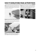
Section 14: Installing the Aileron and/or Quad Flap Linkages
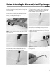
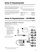
Step 3. The control horn should be positioned so the holes that
the clevis connects onto are over the centerline of the hinge line
of the control surface.
Once satisfied with the horn location (it should be a straight line
from the servo arm to the horn), mark the location with a felt-
tipped pen. You will note the servo is positioned at an angle to
the wing, but is 90 degrees to the hinge line.
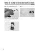
Step 4. Using a 1/16" drill bit, drill the screw holes for mount-
ing the control horn.
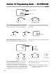
Step 5. Attach the control horn to the aileron (flap) using
the screws and the control horn backplate. Be careful not to
accidentally puncture the covering with the screwdriver.
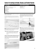
Step 6. Thread a 2-56 clevis on the end of one of the threaded
rods. Screw the clevis on 7-10 turns. Install the clevis with wire
on the control horn into the third hole from the mounting base.
Be sure to install the clevis keeper over the clevis.
Step 7. With the linkage attached to the control horn, center the
control surface and hold the linkage wire directly over the elec-
tronically centered servo arm. Place a mark on the rod directly
over the hole (second hole from the end of arm) in servo control
arm that it will connect too.
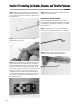
Step 8. Make a 90-degree bend in the rod at the location you
just marked and cut off the excess rod leaving 1/4" of rod past
the 90-degree bend.
CONTINUED