
Instruction manual

43
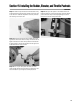
Section 15: Installing the Rudder, Elevator, and Throttle Pushrods
• Fuselage
• 30" pushrod wire, 2-56 threaded on one end (2)
• 16" pushrod wire, 1.5mm (throttle)
• Control horn (2)
• Wire keeper (2)
• Clevis (2)
• Easy connector
• Clevis keeper (2)
• Felt-tipped pen/pencil
• Hobby knife
• Needle-nose pliers
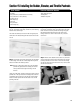
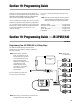
Step 1. Locate one of the long 30" pushrod wires threaded on
one end, a 2-56 clevis, wire keeper, control horn, and mounting
hardware and a clevis keeper.
The rudder and elevator push rods are made using these parts
shown below. The throttle linkage will be made from the shorter
16" rod.
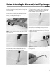
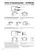
Step 2. Note that the pushrod wire guide tubes are preinstalled
in the fuselage. On the aft end of the fuselage find the pushrod
exits for the rudder and elevator pushrods.
Hint: Slide one of the pushrod wires into to the preinstalled
pushrod wire guide tubes and carefully push the end
of the pushrod wire through the covering over the
exit hole.
Using your hobby knife, carefully cut away the covering over the
pushrod exit on the top left side of the fuselage next to the verti-
cal stabilizer and the opening on the right side of the fuselage
where the elevator pushrod will exit. Be careful not to cut the
pushrod guide tube.
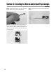
Step 3. To get the required length of the pushrod wire, it will
be necessary to thread the clevis on/off the pushrod wire a few
times. Insert one of the 30" pushrod wires through the guide
tube with the threads exiting the tube at the aft end of the
fuselage. Screw on a clevis 7-10 turns and snap it onto the
control horn.
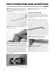
Step 4. With the clevis attached to the control horn, center the
control surface and hold the pushrod wire directly over the elec-
tronically centered servo arm. Place a mark on the rod directly
over the hole (second hole from the end of arm) in servo control
arm that it will connect to.
Parts Needed Tools and Adhesives Needed