
Instructions / Assembly
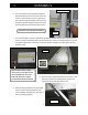

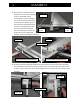
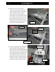
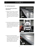
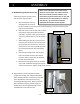
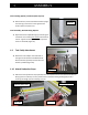
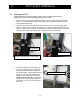
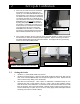
Table Of Contents

1 ASSEMBLY
13
Figure 27b
Right Side, longer stops
Left Side, shorter stops
Figure 27a
Free-Standing Option (continued from Step 18):
24. With assistance, lift the assembled machine upright
onto the legs, and move it to the approximate
location where it will be used.
Final Assembly, Both Mounting Options
25. Adjust the Center Adjustable Leg by unscrewing the
round foot until it makes firm contact
with the floor
surface. Tighten the locking nut after proper floor
contact is achieved (Figure 25).
1.9 Tool Caddy Attachment
26. Mount the Tool Caddy to the underside of
the right end of the Horizontal Material Bar.
Attach with two (2) Philips head screws and
washers provided (Figure 26).
1.10 Attach Production Stops
27. Slide each of the production stops (Box #3) onto the respective ends of the Horizontal Material
Bar (Figures 27a and 27b). You may need to loosen the black locking knob slightly to aid in
inserting the wedge into the matching channel.
Figure 25
Figure 2
6