
Instructions / Assembly


Page 1
INSTALLATION INSTRUCTIONS
Gas Changeover Kit
Natural to Regulated LP/Propane (Kit #11K50)
For A80, 80G1, A93, A95, 92G1 and 95G1 units
WARNING
In the U.S., this conversion kit is to be installed by a licensed professional service technician
(or equivalent) or other qualified agency in accordance with the manufacturer's instructions
and all codes and requirements of the authority having jurisdiction. If the information in
these instructions is not followed exactly, a fire, an explosion, or production of carbon mon
oxide may result, causing property damage, personal injury or loss of life. The qualified
agency is responsible for the proper installation of the kit. The installation is not proper and
complete until the operation of the converted furnace is checked as specified in the furnace
manufacturer's instructions supplied with the kit.
MULTI
-
POSITION
GAS
FURNACE
507369-02
02/2016
Supersedes 507369-01
KIT CONTENTS:
Package 1 of 1 contains the following:
12 -Main burner orifices (0.034)
1 - Gas converter sticker
1 - Nameplate conversion sticker
1 - Bag assembly containing:
1- Gas valve regulator spring
1- Low gas inlet pressure switch
1- Gas valve inlet brass fitting
1- Wiring harness
APPLICATION
Use natural to LP/Propane gas conversion kit 11K50 to
convert units from natural gas to LP/Propane.
INSTALLATION
CAUTION
As with any mechanical equipment, personal injury can
result from contact with sharp sheet metal edges. Be
careful when you handle this equipment.
CAUTION
Gas valve conversion kit MUST be installed BEFORE
the unit is fired using LP/propane gas. Unit damage
WILL OCCUR if the unit is fired using LP/propane gas
with the original natural gas orifices.
1 - Set the thermostat to the lowest setting. If the gas
supply line has been connected, shut off the gas
supply to the furnace, then disconnect the electrical
power.
2 - Remove the heating compartment access panel.
Turn the automatic gas valve switch to the OFF
position. See figures 2 and 3.
3 - Disconnect the gas supply and the two wires at the
gas valve.
4 - Remove the burner box cover (if equipped). Remove
the four manifold securing screws. Slide the
manifold/gas valve assembly out of the burner box.
5 - Replace the burner orifices with the provided gas
orifices. Torque to approximately 35 in-lbs. Do not
use sealant on orifices. Figures 4 and 5 show
manifold/gas valve assembly.
IMPORTANT
DO NOT use pipe dope or any pipe sealant on gas ori
fice threads.
6 - Replace the gas valve regulator spring with the
provided regulator spring. See figure 6.
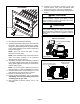
7 - A80 and 80G1 units with Nox inserts being
converted from natural to LP /Propane.
a - Remove the burner box assembly from the
vestibule panel.
b - Remove the screws which secure each of the NO
x
inserts to the clamshell. Remove the NO
x
inserts
and reinstall the screws. See figure 1.
c - Re-install burner box assembly.
Litho U.S.A.