Item #1001 238 144 Model #CF544H-PEH USE AND CARE GUIDE CLARKSTON 44 INCH CEILING FAN Questions, problems, missing parts? Before returning to the store, call Customer Service 1-877-527-0313 HOMEDEPOT.
Table of Contents Table of Contents ..........................................................2 Operation ......................................................................11 Safety Information .........................................................2 Care and Cleaning .......................................................11 Warranty .........................................................................3 Troubleshooting ..........................................................
Warranty We warrant the fan motor to be free from defects in workmanship and material present at time of shipment from the factory for a period of 15 years after the date of purchase by the original purchaser. We also warrant that all other fan parts, excluding any glass or acrylic blades, to be free from defects in workmanship and material at the time of shipment from the factory for a period of one year after the date of purchase by the original purchaser.
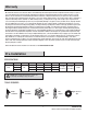
Pre-Installation (continued) HARDWARE INCLUDED NOTE: Hardware shown to actual size unless noted otherwise in the table below.
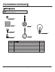
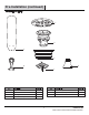
Pre-Installation (continued) PACKAGE CONTENTS C D A E G B F Part Quantity Part Description Quantity A Blade 5 E Fan housing 1 B Blade bracket 5 F Light kit assembly 1 C Mounting bracket 1 G Glass shade 3 D Fan motor assembly 1 Description 5 HOMEDEPOT.COM Please contact 1-877-527-0313 for further assistance.
Installation MOUNTING OPTIONS WARNING: To reduce the risk of fire, electric shock, or personal injury, mount the fan to an outlet box marked acceptable for fan support using the screws provided with the outlet box. An outlet box commonly used for the support of lighting fixtures may not be acceptable for fan support and may need to be replaced. If in doubt, consult a qualified electrician.
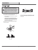
Assembly — Hanging the Fan 1 2 Installing the mounting bracket to the electrical box □ WARNING: To reduce the risk of fire, electric shock or other personal injury, mount the fan only to an outlet box or supporting system marked acceptable for fan support and use the mounting screws provided with the outlet box.
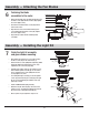
Assembly — Hanging the Fan (continued) 3 Making the electrical connections □ WARNING: To avoid possible electrical shock, be sure electricity is turned off at the circuit breaker or main fuse box before wiring. If you wish to install an optional wall control, use this diagram as a guide but refer to the installation manual for the wall control for the correct color and wire connections.
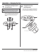
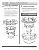
Assembly — Hanging the Fan (continued) 4 5 Attaching the fan motor assembly to the mounting bracket □ Remove one of the four screws (TT) on the mounting bracket (C) and loosen, but do not remove, the other three screws (TT). □ Remove the motor assembly (D) from the J hook. Finishing the fan installation □ Align the four large screwheads (UU) pre-locked on the fan housing (E) to the key holes (1) of the mounting bracket (C).
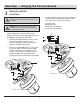
Assembly — Attaching the Fan Blades 6 Fastening the blade assemblies to the motor □ Attach the fan blades (A) to the blade bracket (B) using the blade screws (AA) and fiber washers (BB). Tighten the screws (AA) securely. AA □ Remove the ten blade bracket screws (CC) from the bottom of the motor. BB □ Align the motor holes to the blade bracket (B) and secure with the blade bracket screws (CC). Tighten the screws (CC) securely. A □ Repeat this procedure with the remaining blade assemblies.
Operation Turn on the power and check the operation of your fan. There are two pull chains available in your fan. The fan pull chain controls the fan speed as follows: 1 pull- High, 2 pulls- Medium, 3 pulls- Low, and 4 pulls- Off. The light kit pull chain turns the light “ON” or “OFF” The reverse switch is located on the surface of the switch housing. This switch controls directions: forward (switch down) or reverse (switch up).
Troubleshooting WARNING: Ensure the power is off at the electrical panel box before you attempt any repairs. Refer to the section “Making the Electrical Connections” on page 8. Problem The fan will not start. The fan sounds noisy. The fan wobbles. Solution □ Check the main and branch circuit fuses or breakers. □ Check the line wire connections to the fan and switch wire connections in the switch housing.
Service Parts AA EE D BB E FF A CC F B GG DD C G Part Description Part Description A Blade AA Blade screw B Blade bracket BB Fiber washer C Mounting bracket CC Blade bracket screw D Fan motor assembly DD Plastic wire nut E Fan housing EE Fan pull chain fob F Light kit assembly FF Light kit pull chain fob G Glass shade GG 60W A15C bulb 13 HOMEDEPOT.COM Please contact 1-877-527-0313 for further assistance.
Questions, problems, missing parts? Before returning to the store, call Customer Service 1-877-527-0313 HOMEDEPOT.COM Retain this manual for future use.
Ítem #1001 238 144 Modelo #CF544H-PEH GUÍA DE UTILIZACIÓN Y MANTENIMIENTO CLARKSTON VENTILADOR DE TECHO DE 44 PULGADAS ¿Preguntas, problemas, partes perdidas? Antes de regresar al almacén por favor llame al Servicios de Cliente 1-877-527-0313 HOMEDEPOT.
Lista de Contenidos Lista de Contenidos ...................................................... 2 Operación .....................................................................11 Información de Seguridad ............................................ 2 Cuidado y Limpieza .....................................................11 Garantía ..........................................................................3 Solución de averías .....................................................
Garantía Garantizamos que el motor del ventilador está libre de los defectos de calidad y de material por el tiempo de salir de la fábrica y después de la fecha de compra por el cliente original. También garantizamos que todas las otras piezas del ventilador, excluyendo las hojas de vidrio o de acrílico, cuales está libres de los defectos de calidad y de material en el momento de salir de la fábrica por un período de un año a partir de la fecha de compra por el comprador original.
Instalación Previa (continuada) HERRAMIENTAS INCLUIDAS NOTA: Las medidas de las herramientas se demuestran en la lista siguiente, salvo las otras observaciones.
Instalación Previa (continuada) CONTENIDOS DE PAQUETE C D A E G B F Parte Cantidad Parte A Descripción Hoja 5 E Cáscara de ventilador 1 B Soporte de hoja 5 F Conjunto de luz 1 C Soporte de montaje 1 G Cubierta de vidrio 3 D Conjunto de motor de ventilador 1 5 Descripción Cantidad HOMEDEPOT.COM Por favor entre en contacto con 1-877-527-0313 para más ayuda.
Instalación OPCIONES DE MONTAJE ADVERTENCIA: Para reducir los peligrosos de fuego, choque eléctrico o las lesiones personales, por favor monte el ventilador en una caja de salida disponible al soporte de ventilador utilizando los tornillos proporcionados con la caja de salida. Generalmente una caja de salida que se utiliza para el soporte de los equipos de iluminaciones no puede ser disponibles al soporte de ventilador y debe reemplazarse. Si hay dudas, por favor consulte a un electricista cualificado.
Ensamblado – Colgar el ventilador 1 2 Instale el soporte de montaje en la caja eléctrica □ ADVERTENCIA: PARA REDUCIR EL RIESGO DE FUEGO, DESCARGA ELÉCTRICA O LESIONES PERSONALES, MONTE EL VENTILADOR A UNA TOMA DE CORRIENTE MARCADA COMO COMPATIBLE PARA SOPORTAR UN VENTILADOR CON LOS TORNILLOS INCLUIDOS EN LA TOMA DE CORRIENTE.
Ensamblado – colgar el ventilador (continuada) 3 Haga las conexiones eléctricas □ ADVERTENCIA: Para evitar el choque eléctrico, por favor asegúrese de apagar la electricidad del interruptor de circuito o de la caja fusible principal antes del cableado.
Ensamblado – colgar el ventilador (continuada) 4 5 Fije el conjunto de motor de ventilador en el soporte de montaje Complete la instalación de ventilador □ Quite uno de los cuatro tornillos (TT) en el soporte de montaje (C) y lo afloje, pero no quite, los otros tres tornillos (TT) □ Alinee las cabezas de tornillos largas (UU) que se han bloqueado previamente en la cáscara de ventilador (E) en los agujeros de llave (1) del soporte de montaje(C). □ Quite el conjunto de motor (D) del gancho J.
Ensamblado — Fije las hojas de ventilador 6 Sujete los conjuntos de hoja en el motor □ Fije las hojas de ventilador (A) en el soporte de hoja (B) por utilizando los tornillos de hoja (AA) y las arandelas de fibra (BB). Apriete los tornillos (AA) firmemente. AA □ Quite los diez tornillos de soporte de hoja (CC) desde el fondo de motor. BB □ Alinee los agujeros de motor en el soporte de hoja (B) y los fije con los tornillos de soporte de hoja (CC). Apriete los tornillos (CC) firmemente.
Operación Encienda la fuente eléctrica y verifique la operación del ventilador. Hay dos cadenas de tirada disponibles en el ventilador. La cadena del ventilador controla la velocidad al mismo de la siguiente manera: 1 tirada – Alta, 2 tiradas – Mediana, 3 tiradas – Baja, y 4 tiradas – Apagada. La cadena del juego de luz se turna a la luz entre "ON" o "OFF" El interruptor inverso se situa en la superficie de la cáscara de interruptor.
Solución de averías ADVERTENCIA: Asegúrese de que la fuente eléctrica se apague en la caja de panel eléctrico antes de hacer las reparaciones. Y refiérase a la sección de ¨Hacer las Conexiones Eléctricas¨ en la págia 8. Problema El ventilador no funciona El ventilador emiteruido Solución □ Revisar los fusibles o interruptores de circuitos. □ Verificar las conexiones de cables de linea al ventilador y conexiones de cable del interruptor.
Partes de Servicios AA EE D BB E FF A CC F B GG DD C G Parte Descripción Parte Descripción A Hoja AA Tornillo de hoja B Soporte de hoja BB Arandela de fibra C Soporte de montaje CC Tornillo de soporte de hoja D Conjunto de motor de ventilador DD Tuerca de alambre plástica E Cáscara de ventilador EE Tirador de cadena de ventilador F Conjunto de luz FF Tirador de cadena de luz G Cubierta de vidrio GG Foco 60W A15C 13 HOMEDEPOT.
¿Preguntas, problemas, partes perdidas? Antes de regresar al almacén por favor llame al Servicios de Cliente 1-877-527-0313 HOMEDEPOT.COM Por favor mantenga el manual para la utilización en el futuro.