Item #1001 028 991 Model #SW1422 USE AND CARE GUIDE MERWRY LED 52 INCH CEILING FAN Questions, problems, missing parts? Before returning to the store, call Home Decorators Collection Customer Service 8 a.m. - 6 p.m., EST, Monday-Friday 1-800-986 3460 HOMEDEPOT.
Table of Contents Table of Contents ..........................................................2 Safety Information .........................................................3 Warranty .........................................................................4 Pre-installation .............................................................. 4 Specifications .......................................................................... 4 Tools Required .................................................................
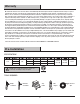
Safety Information □ Read and save these instructions. □ To reduce the risk of electric shock, ensure electricity has been turned off at the circuit breaker or fuse box before beginning. □ All wiring must be in accordance with the National Electrical Code “ANSI/NFPA 70-1999” and local electrical codes. Electrical installation should be performed by a qualified licensed electrician. □ The outlet box and support structure must be securely mounted and capable of reliably supporting a minimum of 35 lbs.
Warranty We warrant the fan motor to be free from defects in workmanship and material present at time of shipment from the factory for a period of lifetime after the date of purchase by the original purchaser. We also warrant that all other fan parts, excluding any glass or acrylic blades, to be free from defects in workmanship and material at the time of shipment from the factory for a period of two year after the date of purchase by the original purchaser.
Pre-Installation (continued) HARDWARE INCLUDED NOTE: Hardware shown to actual size unless noted otherwise in the table below.
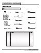
Pre-Installation (continued) PACKAGE CONTENTS D K E F L G A M H B N I J C Part Description O Description Quantity 5 Part I Light kit plate (preassembled) Quantity 1 A Blade B Mounting bracket 1 J 17-W LED assembly (preassembled) 1 C Canopy 1 K 1 D E Canopy cover Hanger ball (preassembled) 1 1 L M Glass shade Receiver F Downrod (preassembled) 1 G Couping cover 1 H Fan motor assembly 1 6 Remote control 1 1 N Remote control holder 1 O 12V Battery 1
Installation MOUNTING OPTIONS WARNING: To reduce the risk of fire, electric shock, or personal injury, mount the fan to an outlet box marked acceptable for fan support using the screws provided with the outlet box. An outlet box commonly used for the support of lighting fixtures may not be acceptable for fan support and may need to be replaced. If in doubt, consult a qualified electrician.
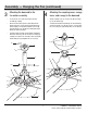
Assembly — Attaching the Fan Blade 1 □ Attaching the fan blade to the fan assembly AA BB Attach the five fan blades (A) to the fan motor assembly (H) using the blade screws (AA) and fiber washers (BB), three for each blade. Tighten all screws securely. NOTE: When installing the blades, ensure the sides with “THIS SIDE UP” face the ceiling.
Assembly — Hanging the Fan (continued) 3 4 Attaching the downrod to the fan motor assembly Attaching the coupling cover, canopy cover, and canopy to the downrod □ Loosen the two set screws (JJ) from the fan motor assembly (H) coupling. □ Slip the coupling cover (G), canopy cover (D), and canopy (C) onto the downrod (F). □ Remove the hitch pin (GG) and lock pin (HH) from the downrod (F).
Assembly — Hanging the Fan (continued) 5 Hanging the fan motor assembly from the mounting bracket □ Lift the fan motor assembly (H) into position, and place the hanger ball (E) into the mounting bracket (B). Rotate the fan motor assembly (H) until the check groove drops into the registration slot (NN) and seats firmly. The downrod (F) should not rotate if this is done correctly.
Assembly — Hanging the Fan (continued) 7 Making the electrical connections 1 WARNING: To avoid possible electrical shock, ensure the electricity is turned off at the circuit breaker or main fuse box before wiring. WARNING: Check to see that all connections are tight, including the ground, and that no bare wire is visible at the wire nuts, except for the ground wire. Black White Black White Follow the steps below to connect the fan to your house supply wires.
Assembly — Hanging the Fan (continued) 8 Securing the fan motor assembly to the mounting bracket □ Remove one screw (KK) from the mounting bracket (B) and loosen the other screw (KK) approximately 1/4 turn. □ Carefully raise the canopy (C) up to the mounting bracket (B), and ensure the loosened screw (KK) is inserted into the key hole on the canopy (C). Rotate the canopy (C) clockwise.
Assembly — Installing the Light Kit 9 10 Installing the light kit plate CAUTION: To reduce the risk of electric shock, disconnect the electrical supply circuit to the fan before installing the light kit. □ Remove the 17-W LED assembly (J) from the light kit plate (I) by removing three light kit plate screws (MM). Set these screws (MM) aside for use later. □ Remove one of three screws (LL) from the fan motor assembly (H) mounting ring and loosen, but do not remove, the other two screws (LL).
Operation REMOTE CONTROL OPERATING INSTRUCTIONS Install a 12V battery (O) into the remote control (M). To prevent damage to the remote control, remove the battery if not used for long periods of time. M WARNING: Do not short-circuit, disassemble, heat up, connect improperly, or dispose of used batteries in fire. Do not recharge or mix batteries with used or other battery types. Immediately remove used batteries. Restore power to the ceiling fan and test for proper operation.
Operation (continued) INSTALLING THE REMOTE CONTROL HOLDER □ Attach the remote control holder (N) with the two remote control holder mounting screws (DD). N DD Care and Cleaning Do □ Do not Check the support connections, brackets, and blade attachments twice a year. Ensure they are secure. Because of the fan’s natural movement, some connections may become loose over time. It is not necessary to remove the fan from the ceiling. □ Clean your fan periodically.
Troubleshooting WARNING: Ensure the power is off at the electrical panel box before you attempt any repairs. Refer to the section “Making the Electrical Connections” on page 11. Problem The fan will not start. The fan sounds noisy. The remote control is not working. The fan wobbles. Solution □ Check main and branch circuit fuses or breakers. □ Check line wire connections to the fan and switch wire connections in the switch housing.
Service Parts AA H A GG HH I BB II J B K JJ CC C L D E F M DD KK EE LL FF MM N G O Description Part Description AA Blade screw BB Fiber washer G H Blade Mounting bracket Canopy Canopy cover Hanger ball Downrod Couping cover Fan motor assembly I Light kit plate II Hanger ball set screw J 17-W LED assembly JJ K Glass shade KK Fan motor assembly coupling set screw Mounting bracket screw L Receiver LL Fan motor assembly mounting ring screw M Remote control MM Ligh
Questions, problems, missing parts? Before returning to the store, call Home Decorators Collection Customer Service 8 a.m. - 6 p.m., EST, Monday-Friday 1-800-986 3460 HOMEDEPOT.COM/HOMEDECORATORS Retain this manual for future use.
Ítem #1001 028 991 Modelo #SW1422 GUÍA DE USO Y MANTENIMIENTO VENTILADOR DE TECHO MERWRY LED, DE 1,32 M ¿Preguntas, problemas o piezas faltantes? Antes de regresar a la tienda, llama al servicio al cliente de Home Decorators Collection, de lunes a viernes entre 8 a.m. y 6 p.m. (hora estándar del Este). 1-800-986 3460 HOMEDEPOT.COM/HOMEDECORATORS GRACIAS POR TU COMPRA crear productos de calidad diseñados para mejorar tu hogar.
Lista de Contenidos Lista de Contenidos ...................................................... 2 Información de Seguridad ............................................ 3 Garantía ..........................................................................4 Instalación Previa .......................................................... 4 Especificaciones ...................................................................... 4 Herramienta Necesarias ..........................................................
Información de Seguridad □ Lea y guarde estas instrucciones. □ Para reducir el riesgo de eléctrocución, asegurarse de que la eléctricidad se ha desactivado en el cortacircuitos o caja de fusibles antes de comenzar. Todos los cables deben cumplir con el Código Eléctrico Nacional “ANSI/NFPA 70-1999” y los códigos eléctricos locales. La instalación eléctrica debería realizarla un electricista profesional cualificado.
Garantía Garantizamos que el motor del ventilador está libre de los defectos de calidad y de material por el tiempo de salir de la fábrica y después de la fecha de compra por el cliente original. También garantizamos que todas las otras piezas del ventilador, excluyendo las hojas de vidrio o de acrílico, cuales está libres de los defectos de calidad y de material en el momento de salir de la fábrica por un período de dos año a partir de la fecha de compra por el comprador original.
Instalación Previa (continuada) HERRAMIENTAS INCLUIDAS NOTA: Las medidas de las herramientas se demuestran en la lista siguiente, salvo las otras observaciones.
Instalación Previa (continuada) CONTENIDO DE PAQUETE D K E F L G A M H B N I J C Descripción O Descripción Cantidad 5 Parte I Placa de juego de luz (premontado) Soporte de montaje 1 J Conjunto LED 17-W (premontado) 1 C Tapa 1 K Sombra de vidrio 1 D E Tapa de cubierta L M Receptor Bola de suspensión (premontado) 1 1 Mando a distancia 1 1 F Varilla (premontado) 1 N Soporte de mando a distancia 1 G Cubierta de acoplamiento 1 O Batería 12Vcc 1 H Conjunto de motor de v
Instalación OPCIONES DE MONTAJE ADVERTENCIA: Para reducir los peligros de fuego, choque eléctrico o las lesiones personales, por favor monte el ventilador en una caja de salida disponible al soporte de ventilador utilizando los tornillos proporcionados con la caja de salida. Generalmente una caja de salida que se utiliza para el soporte de los equipos de iluminaciones no puede ser disponibles al soporte de ventilador y debe reemplazarse. Si hay dudas, por favor consulte a un electricista cualificado.
Ensamblado — Fije las aspas de ventilador 1 Sujete los aspa en el conjunto de motor de ventilador □ AA BB Fije las cinco aspas del ventilador (A) en el conjunto del motor del ventilador (H) utilizando los tornillos de aspa (AA) y las arandelas de fibra (BB), los tres para cada aspa. Y atornille todos los tornillos firmemente. NOTA: A la instalación de las aspas, por favor asegúrese de que los lados con “THIS SIDE UP” enfrente al techo.
Ensamblado – colgar el ventilador (continuada) 3 □ Afloje los dos tornillos de fijación (JJ) del acoplamiento del conjunto del motor del ventilador del motor (H). □ Quite el pasador de enganche (GG) y el pasador de bloqueo (HH) de la varilla (F). Quite la bola de suspensión (E) de la varilla (F) por aflojando el tornillo de fijación de la bola de suspensión (II), y quitando el pasador transversal (FF), entonces deslizando la bola de suspensión (E) fuera de la varilla (F).
Ensamblado – colgar el ventilador (continuada) Cuelgue el juego de ensamblaje de motor de ventilador desde el soporte de montaje 5 □ Levante el conjunto del motor del ventilador (H) en la posición, y coloque la bola de suspensión (E) en el soporte de montaje (B). Gire el conjunto del motor del ventilador (H) hasta que la ranura de prueba estén en la ranura de registro (NN) y lo coloque firmemente. Debe girar la varilla (F) en caso de falla operación.
Ensamblado – colgar el ventilador (continuada) 6 Haga las conexiones eléctricas 1 ADVERTENCIA: Para evitar el choque eléctrico, por favor asegúrese de apagar la electricidad del interruptor de circuito o de la caja fusible principal antes del cableado. ADVERTENCIA: Verifique todas las conexiones esten bien, incluyendo el alambre a tierra, y no puede ver alambres desnudos en las tuercas de alambre, excepto por alambre a tierra.
Ensamblado – colgar el ventilador (continuada) 8 Fijar el juego de ensamblaje de motor del ventilador al soporte de montaje □ Quite un tornillo (KK) del soporte de montaje (B) y afloje el otro tornillo (KK) por 1/4 de vuelta más o menos. □ Levante la tapa (C) con mucho cuidado al soporte de montaje (B), y comprueba que el tornillo aflojado (KK) haya insertado en el agujero de la llave en la tapa (C). Gire la tapa (C) en sentido horario.
Ensamblado — Instale el Conjunto de Luz 9 10 Instalación de la placa de juego de luz PRECAUCIÓN: Para reducir el peligro del choque eléctrico, por favor desconecte el circuito de alimentación eléctrica al ventilador antes de la instalación del juego de luz. □ Quite el conjunto LED 17-W (J) de la placa de juego de luz (I) por sacando los tres tornillos de placa de juego de luz (MM). Y coloque los tornillos (MM) al lado para la utilización en la futura.
Operación Instrucción de operación de mando a distancia Instale una batería tipo A23 de 12 Vcc (O) en el control remoto (M). Para evitar los daños del control remoto, por favor quita la batería si no la utiliza por un largo tiempo. M ADVERTENCIA: No debe cortocircuito, desmontar, calentar, conectar incorrectamente o arrojar las baterías usadas al fuego. No debe recargar ni mezclar las baterías con las usadas o de otros tipos. Y debe quitar las baterías usadas inmediatamente.
Operación (continuada) INSTALACIÓN DEL SOPORTE DE MANDO A DISTANCIA □ Coloque el soporte del mando a distancia (N) con dos tornillos adjuntos (DD). N DD Cuidado y Limpieza Hacer No pueda hacer □ □ No pueda utilizar aguas a la limpieza. El agua pueda dañar el motor, la madera o causar un choque eléctrico posiblemente. □ No pueda aplicar aceite en el ventilador o el motor. Los rodamientos de bolas del motor han sido lubricados permanentemente.
Solución de averías ADVERTENCIA: Asegúrese de que la fuente eléctrica se apague en la caja de panel eléctrico antes de hacer las reparaciones. Y refiérase a la sección de ¨Hacer las Conexiones Eléctricas¨ en la págia 11. Problema El ventilador no funciona El ventilador emiteruido Solución □ Revisar los fusibles o interruptores de circuitos. □ Verificar las conexiones de cables de linea al ventilador y conexiones de cable del interruptor.
Partes de Servicios AA H A GG HH I BB II J B K JJ CC C L D E F M DD KK EE LL FF MM N G O Parte Descripción Parte Descripción A Aspa AA Tornillo de aspa B Soporte de montaje BB Arandela de fibra C Tapa Tapa de cubierta CC Conjunto de balanceo D DD Tornillos de montaje para soporte del mando a distancia E Bola de suspensión EE Tuerca de alambre plástica F Varilla FF G H Cubierta de acoplamiento GG HH El pasador transversal Pasador de enganche I Placa de jueg
¿Preguntas, problemas o piezas faltantes? Antes de regresar a la tienda, llama al servicio al cliente de The Home Depot de lunes a viernes, de 8 a.m. a 6 p.m. (hora estándar del Este) 1-800-986-3460 HOMEDEPOT.COM/HOMEDECORATORS Conserva este manual para uso futuro.