
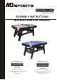
Instructions / Assembly


Español
www.themdsports.com
1616603
9
(Continúe en la siguiente página.)
(Continued on the next page.)
English
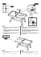
FIG. 5
FIG. 6
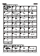
X 2
14
X 2
11
A6
X 2
X 2
17
FIG.5
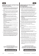
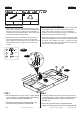
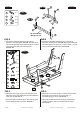
11. Attach the the FIG. 2B Assembly to the Mainframe (#1)
using two Screws (#A6) and two End Caps (#17).
See FIG. 5.
12. Thread the Wire of Electronic Scorer (#7) through the
opening of the Mainframe to the Connect Box (#8),
and then plug the Scorer wire into the Connect Box
(#8). See FIG. 5A.
13. Tear off the backside papers of the Felt Pads (#11) and
stick them at the bottom of the Pushers (#14).
See FIG. 5B.
FIG.5
11. Adjunte el Montaje FIG. 2B a las Unidad Principal (#1)
usando 2 Tornillos (#A6) y 2 Gorras Final (#17).
Vea las FIG. 5.
12. Enhebre el Cable del Marcador Electrónico (#7) por las
aberturas del Unidad Principal a la Caja de Conexión
(#8), y luego enchufe el cable del Marcador a la Caja de
Conexión (#8). Vea la FIG. 5A.
13. Arranque la trasera del papel de la Almohadilla de Fieltro
(#11) y péguelos en el fondo de Golpeadors (#14).
Vea la FIG. 5B.
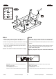
FIG.6
14. Place the Table Tennis Surface (#6) onto the hockey
surface. See FIG. 6.
FIG.6
14. Coloque las Superficies de Mesa de Tenis (#6) sobre la
superficie de hockey. Vea las FIG. 6.
14
11
FIG. 5B
A6
17
1
7
FIG. 2B Assembly
/ Montaje FIG. 2B
Scorer wire
/ Cable de
marcador
Goal wire
/ Cable de gol
X 1
6
1
6
8
FIG. 5A
1