
Instructions / Assembly
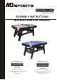


www.themdsports.com
1616603
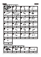
7
(Continúe en la siguiente página.)
(Continued on the next page.)
Español
English
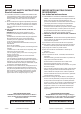
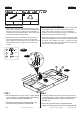
FIG.2
5. Conecte los Marcador Electrónico (#7) y Soporte de
Marcador - B (#18) juntos. Vea FIG. 2A. Adjunte el Montaje
FIG. 2A al Soporte de Marcador - A (#16) usando 1 Tornillo
(#A7) por Soporte de Marcador. See FIG. 2B.
FIG.2
5. Connect the Electronic Scorer (#7) and Scorer
Supports - B (#18) together. See FIG. 2A. Then attach
the FIG. 2A Assembly to the Scorer Supports - A (#16)
using one Screw (#A7) per Scorer Support.
See FIG. 2B.
FIG. 2
X 2
16
X 2
18
A7
X 8
7
X 1
16
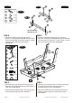
FIG. 2B
FIG. 2A
A7
16
A7
FIG. 2A Assembly
/ Montaje FIG. 2A
7
18
A7
A7
18
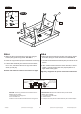
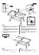
FIG.3
6. Attach the Right Legs (#3) and Left Legs (#2) to the
Mainframe using three Bolts (#A2) and three Washers
(#A3) per Leg. See FIG. 3.
7. Attach the Side Leg Panels (#5) to the Legs using four
Screws (#A6) per Side Leg Panel. See FIG. 3.
FIG.3
6. Adjunte la Piernas Derecha (#3) y Piernas Izquierda (#2)
al Unidad Principal usando 3 Cerrojos (#A2) y 3
Arandelas (#A3) por Pierna. Vea la FIG. 3.
7. Adjunte el Paneles de Pierna Lateral (#5) a las Piernas
usando 4 Tornillos (#A6) por Panel de Pierna Lateral.
Vea la FIG. 3.
FIG. 3
X 2
X 2
X 2
X 1
1
2
3
5
X 12
A2
X 12
A3
X 8
A6
X 1
P1
X 12
P3
1
3
3
2
5
5
A6
A2
A3
P1
P3
2
X 4P6
P6