
User manual


SMD Circuit Breaker
Item no. 191779
Intended Use
The SMD circuit breaker is used to switch special functions in the model construction area, e.g. spotlights,
ashlights, buzzer, siren, water pump on and off.
It is connected to a free channel of a receiver or alternatively in parallel to a servo. A small setting potentio-
meter permits determination of the switching point.
The safety notes and all other information in these operating instructions always have to be observed.
This product complies with the statutory national and European requirements. All company names and pro-
duct names are trademarks of their respective owners. All rights reserved.
Scope of Delivery
• SMD circuit breaker
• Operating Instructions
Safety Information
In case of damage caused by non-compliance with these operating instructions, the war-
ranty/guarantee will expire. We do not assume any liability for consequential damage!
Nor do we assume any liability for damage to property or personal injury caused by impro-
per use or failure to observe the safety instructions. In such cases the guarantee/warranty
will expire!
• The unauthorized conversion and/or modication of the product is prohibited for safety and approval re-
asons (CE).
• This product is not a toy and not suitable for children.
• The product will be destroyed if it gets damp or wet.
• Do not overload the SMD-circuit breaker (see „Technical Data“).
• Keep enough distance from the receiver and motors/speed controllers. Do not place the connection cables
close to the receiver aerial.
• Handle the product with care; impacts, shock or fall even from low heights will damage it.
• Do not leave packaging material unattended. It may become a dangerous toy for children. When operating
vehicles, make sure that no body parts or other objects are inside the danger area of moving parts. Risk
of injury!
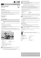
Connections and Control Elements
1 Servo cables
Yellow/white/orange cable: Control signal
Red cable: Operating voltage (4.5 - 6 V/DC)
Brown/black cable: Minus/GND
2 Operating voltage, 5 - 18 V/DC
3 Connection for consumers/load, directly connected to (2) (+)
4 Rotary potentiometer for setting the switching point
5 Connection for consumer/load
6 Minus/GND
The SMD circuit breaker is only suitable for an operating voltage of 4.5 - 6 V/DC that it receives
directly from the recipient via the servo cable (1).
The control voltage for the consumer, in contrast, may be in the 5 - 18 V/DC range.
Observe that the connection (6) and Minus/GND of the servo cable are directly connected (impor-
tant if you tap the switching voltage of a multi-cell rechargeable battery).
Connection and Installation
The connection must only be established in the voltage-free condition. Only when all connections
are made must the operating voltage be activated.
Always ensure that no short circuits are created in connection. For example, use suitable shrink
hoses to protect solder connections.
Place all cables so that they cannot be damaged by sharp edges. Observe that the cables cannot
enter drive parts. Secure the cables, e.g., with cable fasteners.
• Connect the two cables (3) and (5) to the consumer. Depending on the connected consumer, observe
correct polarity (plus/+ and minus/-); see chapter „Connections and Control elements“.
• Connect the servo cable (1) e.g. to a free channel of your receiver. Observe correct connection; observe
either the print on your receiver or the information in the corresponding operating instructions.
Alternatively, the servo cable of the SMD circuit breaker can also be switched in parallel with a present
servo or speed controller (e.g. via a Servo-Y cable).
Always observe correct connection here. The colours for the control signal or for minus/GND may vary
depending on servo/speed controller:
Yellow/white/orange cable: Control signal
Red cable: Operating voltage
Brown/black cable: Minus/GND
• The cables (2) and (6) are used for connection to the control voltage. Always observe correct polarity
(observe plus/+ and minus/-), since else the SMD circuit breaker will be destroyed, loss of warranty/
guarantee!
The SMD circuit breaker is only suitable for an operating voltage of 4.5 - 6 V/DC that it receives
directly from the recipient via the servo cable (1).
The control voltage for the consumer, in contrast, may be in the 5 - 18 V/DC range.
Observe that the connection (6) and Minus/GND of the servo cable (1) are directly connected
(important if you tap the switching voltage of a multi-cell rechargeable battery).
• Attach the SMD circuit breaker at a suitable location in your model. E.g., use double-sided adhesive tape
or hook-and-loop tape.
If the SMD circuit breaker must be installed in an inaccessible location in the model, set the switching point
before assembly.
Select an assembly site where the SMD circuit breaker is protected from dust, dirt and moisture.
Commissioning
• Check the correct connection again.
• Switch on the transmitter and then the power supply for the receiver and the SMD circuit breaker.
• Use the setting potentiometer to set the desired switching point.
Then preferably use a small plastic screwdriver. Common screwdrivers with a metal tip pose the
danger of short-circuit, which destroys the SMD circuit breaker; loss of warranty/guarantee!
Do not use any force when twisting!
Move the control lever of the channel that belongs to the SMD circuit breaker at your transmitter or activate
the switching channel.
Check the function of the SMD circuit breaker or the connected consumer.
Disposal
Electric and electronic products must not be disposed of in the domestic waste!
Dispose of the product according to the applicable statutory provisions at the end of its service
life.
Technical Data
Operating voltage ..........................................4.5 - 6 V/DC (via servo cable)
Quiescent current consumption .....................Approx. 0.012 mA
Switching voltage ...........................................5 - 18 V/DC
Switching current/permanent current .............max. 1 A
Switching threshold .......................................Adjustable
Dimensions ....................................................25 x 20 x 3.5 mm (L x W x H)
Weight ...........................................................10 g (incl. cable)
Version 02/14
Operating Instructions
www.conrad.com
1
4
+
–
2 3
5
6
These operating instructions are a publication by Conrad Electronic SE, Klaus-Conrad-Str. 1, D-92240 Hirschau
(www.conrad.com).
All rights including translation reserved. Reproduction by any method, e.g. photocopy, microlming, or the capture in
electronic data processing systems require the prior written approval by the editor. Reprinting, also in part, is prohibited.
These operating instructions represent the technical status at the time of printing. Changes in technology and equipment
reserved.
© Copyright 2014 by Conrad Electronic SE.