k Manual ni RL-2 ta m s el ek tro Item no.
English RL-2 Table of contents Getting started............................................................................3 2. Safety instructions.......................................................................5 3. Safe and correct soldering...........................................................7 4. Operation overview.....................................................................9 5. Technical specifications...............................................................9 6.
RL-2 English 1. Getting started How to use this manual ni k This manual gives step-by-step instructions for safe and correct assembly of the kit and fitting and connecting of the ready-built module, and operation. Before you start, we advise you to read the whole manual, particularly the chapter on safety instructions and the checklist for trouble shooting. You will then know where to take care and how to prevent mistakes which take a lot of effort to correct.
English RL-2 Required materials For assembling the kit you need: k an electronic soldering iron (max. 30 Watt) or a regulated soldering iron with a fine tip and a soldering iron stand, a tip-cleaning sponge, a heat-resistant mat, a small side cutter and wire stripper, as necessary a pair of tweezers and long nose pliers, electronic tin solder (0,5 mm. diameter). ni tro For testing the module you need an electric light bulb. el ek In order to connect the module you need wire.
RL-2 English 2. Safety instructions Mechanical hazards Cut wires can have sharp ends and can cause serious injuries. Watch out for sharp edges when you pick up the PCB. Electrical hazards ni k Visibly damaged parts can cause unpredictable danger. Do not use damaged parts: recycle and replace them with new ones. ta m el ek Never perform wiring on a powered module. Assembling and mounting the kit should only be done in closed, clean, dry rooms. Beware of humidity.
English RL-2 Fire risk k Touching flammable material with a hot soldering iron can cause fire, which can result in injury or death through burns or suffocation. Connect your soldering iron or soldering station only when actually needed. Always keep the soldering iron away from inflammable materials. Use a suitable soldering iron stand. Never leave a hot soldering iron or station unattended.
RL-2 English 3. Safe and correct soldering ! Caution: ni ta m tro el ek Use a small soldering iron with max. 30 Watt or a regulated soldering iron. Only use electronic tin solder with flux. When soldering electronic circuits never use soldering-water or soldering grease. They contain acids that can corrode components and copper tracks. Insert the component connecting pins into the PCB´s holes as far as possible without force. The components should be close to the PCB`s surface.
English Cut the wires after soldering directly above the soldering joint with a side cutter. After placing the parts, please double check for correct polarity. Check the PCB tracks for solder bridges and short circuits created by accident. This would cause faulty operation or, in the worst case, damage. You can remove excess solder by putting a clean soldering tip on the spot. The solder will become liquid again and flow from the soldering spot to the soldering tip.
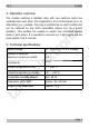
RL-2 English 4. Operation overview Supply voltage 12 - 18 Volt a.c. or d.c. voltage 2 1A el ek Number of switches Maximum current per switch Protected to tro 5. Technical specifications ni k The module switches a bistable relay with two switches which are separate from each other. It is triggered by 12 to 18 Volt direct (d.c.) or alternating (a.c.) voltage. The relay is switched by an earth contact and can be switched by any earth compatible output (e.g. by a points decoder).
English RL-2 6. Assembling the kit You can skip this part if you have purchased a ready-built module. Preparation Put the sorted components in front of you on your workbench. Resistors tro Resistors reduce current. ni k The separate electronic components have the following special features you should take into account in assembling: The value of resistors for smaller power ratings is indicated through colour rings. Every colour stands for another figure.
RL-2 English Bistable relays keep their status after switching – comparable to a switch. Relays which combine two switches in one housing are common as well (shortly 2xUM). The switching between the two connections can be heard clearly because of the resulting clicking sound. k PCB sockets Resistor R1 220 W Diode D1 1N4148 (or similar) Relay el ek Parts list tro ni The widely spread 2,6 mm model railway connectors fit exactly to the sockets.
English RL-2 Assembly Proceed according to the order given in the list below. First solder the components on the solder side of the PCB and then cut the excess wires with the side cutter. Follow the instructions on soldering in section 3. Caution: k ! PCB sockets 2. Resistors 3. Diodes 4. Relays el ek 1. tro ni Several components have to be mounted according to their polarity. When soldering these components the wrong way round, they can be damaged when you connect the power.
RL-2 English 7. Performing a functional test You can perform a functional test with an electric light bulb before mounting the relay circuit board.
English RL-2 8. Connecting the relay circuit board Connecting the power supply ni k If you use a d.c. transformer for the power supply of the relay circuit board, you have to regard the polarity when connecting it, if using an a.c. transformer the polarity is of no importance. If you supply several components by one a.c. transformer you have to be careful to connect all devices with the same polarity.
English el ek Fig. 2: Connections tro ni k RL-2 ta m s It shows as an example, the connection of the relay circuit board to a double purpose light signal.
English RL-2 9. Check list for troubleshooting Parts are getting too hot and/or start to smoke. ! Disconnect the system from the mains immediately! The relay does not switch. Possible cause: The diode D1 is soldered the wrong way. à Swap the mounting direction. tro ni k Possible cause: one or more components are soldered incorrectly. à In case you have mounted the module from a kit, perform a visual check (à section 6.) and if necessary, remedy the faults.
RL-2 English 10. Guarantee bond ni k For this product we issue voluntarily a guarantee of 2 years from the date of purchase by the first customer, but in maximum 3 years after the end of series production. The first customer is the consumer first purchasing the product from us, a dealer or another natural or juristic person reselling or mounting the product on the basis of selfemployment. The guarantee exists supplementary to the legal warranty of merchantability due to the consumer by the seller.
English RL-2 11. EU declaration of conformity This product conforms with the EC-directives mentioned below and is therefore CE certified. ni Connect the transformer only to an approved mains socket installed by an authorised electrician. Make no changes to the original parts and accurately follow the instructions, connection diagrams and PCB layout included with this manual. Use only original spare parts for repairs. tro k 2004/108/EG on electromagnetic.
English ta m s el ek tro ni k RL-2 Page 19
n n n tro http://www.tams-online.de n ni Information and tips: k n n el ek n n n s Warranty and service: ta m Tams Elektronik GmbH Fuhrberger Straße 4 DE-30625 Hannover fon: +49 (0)511 / 55 60 60 fax: +49 (0)511 / 55 61 61 e-mail: modellbahn@tams-online.