Operator’s Manual Original Operating Instructions Chipper Shredders SN GAS/OIL RATIO Includes Model Numbers: 18493 (Viper 212cc) 22752 (Viper 301cc) 22753 (Briggs & Stratton 205cc) 22754 (Kohler 196cc) Get parts online at www.tazztools.com 50:1 P/N: 22180 ECN: 11027 REV2: 12/01/15 © 2015 Ardisam, Inc.
Operator’s Manual Chipper Shredders INTRODUCTION Congratulations on your investment in quality. Thank you for purchasing a Chipper Shredder from Tazz. We have worked to ensure that your product meets the highest standards for usability and durability. With proper care, your Chipper Shredder will provide many years of service. Please read this entire manual before installation and use. Tazz reserves the right to change, alter or improve the product and this document at any time without prior notice.
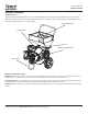
Operator’s Manual Chipper Shredders FEATURES & CONTROLS Control Functions The information below briefly describes the function of individual controls. Operating requires the combined use of several controls applied in specific sequences. To learn what combination and sequence of controls to use for various tasks see the OPERATION section. *For engine features and controls see engine manual.
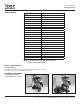
Operator’s Manual Chipper Shredders SPECIFICATIONS CHIPPING CAPACITY APPROXIMATELY 3” (7.6 CM) SHREDDING CAPACITY 1/2”X 18” LONG CHIPPING KNIVES 2 SHREDDING HAMMERS 2 J-HAMMERS; 2 TRIANGLE HAMMERS WASTE REDUCTION RATIO 20:1 START TYPE RECOIL ROTOR MATERIAL STEEL HOPPER DIMENSIONS (IN) 16.75 x 13.
Operator’s Manual Chipper Shredders WARNINGS AND SAFETY PRECAUTIONS Owner’s Responsibility Accurate assembly, and safe and effective use of the chipper shredder is the owner’s responsibility. • Read and follow all safety instructions. • Carefully follow all assembly instructions. • Maintain the chipper shredder according to directions and schedule included in this Tazz operator’s manual. • Ensure that anyone who uses the chipper shredder is familiar with all controls and safety precautions.
Operator’s Manual Chipper Shredders SAFETY DECALS This unit has been designed and manufactured to provide you with the safety and reliability you would expect from an industry leader in outdoor power equipment manufacturing.
Operator’s Manual Chipper Shredders GENERAL OPERATING SAFETY • Read, understand, and follow all instructions in the manual and on the unit before starting • Dress appropriately when operating the chipper shredder. Always wear sturdy footwear and safety goggles. Never wear sandals, sneakers or open shoes, and never operate the chipper shredder with bare feet. Do not wear loose clothing that might get caught in moving parts.
Operator’s Manual Chipper Shredders shredder unit while it is running. Doing so could cause the machine to tip over, and reaching to steady the unit could result in accidental insertion of your hands into the chipper cone or shredder hopper areas. • • • • If your machine comes with a separate engine manual, be sure to read and follow all safety and warning precautions outlined there, in addition to any in this manual.
Operator’s Manual Chipper Shredders Gasoline Fires and Handling Fuel Safely BURNS AND FIRES Use extra care in handling gasoline and other fuels. They are flammable and vapors are explosive. The muffler, muffler guard and other parts of the engine become extremely hot during the operation of the engine. These parts remain extremely hot after the engine has stopped.
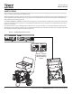
Operator’s Manual Chipper Shredders ASSEMBLY A Install Kick Stand (SEE FIGURE 1) B 1. Position the kick stand (A) underneath the engine with the loop of the kick stand pointing away from the wheel axle (B). 2. Using the four M8-1.25 X 40 bolts, nuts, and eight washers, secure the kick stand to the base plate of the engine. C Install the Wheels (SEE FIGURE 2) 1. Slide the wheel onto the axle (B). FIGURE 2 - Installing the Wheels A. 12 MM Washer 2.
Operator’s Manual Chipper Shredders B C A FIGURE 7 B FIGURE 5 - Installing the Hopper Handle A. M8-1.25 x 20 Hex Flange Bolt and Nut C B. M8-1.25 Hex Nut C. M8 Washer Install Debris Bag A 1. Slide the support rod (A) into the bracket (B). SEE FIGURE 6. Rotate the rod so that it sits below the front tab (C) of the bracket. FIGURES 6 & 7 2. Slide the tabs (B) on the debris bag onto the support rod (A). FIGURE 8 3. Secure the bag connector onto the chipper by rotating the connector until locked in.
Operator’s Manual Chipper Shredders GENERAL OPERATION DANGER Be sure to read all information in the Safety and Operation sections before attempting to operate this unit. Become familiar with all of the controls and how to stop the unit. Check all hardware (bolts, screws, etc) before every use for tightness to be sure machine is in safe working condition. Upon start-up and shut-down, you may hear the metal-to-metal sound of the triangular hammers and J-hammers positioning themselves on the rotor.
Operator’s Manual Chipper Shredders Starting the Engine 1. See engine manual for start up instructions. 2. Ensure engine is running full throttle before beginning chipping operation. On some engines, the throttle may not be adjustable. Stopping the Engine 1. See engine manual for shut down procedure. 2. Stopping the engine is the only way to stop the rotor from turning. With engines equipped with an adjustable throttle, move the throttle to the SLOW position and wait for engine to be running a slow RPM.
Operator’s Manual Chipper Shredders CHIPPING AND SHREDDING RECOMMENDATIONS OPERATION TYPE OF WASTE PERMITTED SIZE LIMITATIONS NOTES Shredding Dry or moist organic material including leaves, plants, flowers, fruits, or vegetables. Branches and twigs up to 1/2” diameter and 18” long. Alternately chip or shred moist green waste with dry waste to avoid plugging of the discharge chute. Process at a feeding rate that allows the rotor to keep up and maintain a high rate of speed.
Operator’s Manual Chipper Shredders MAINTENANCE Schedule & Procedures The following schedule should be followed for normal care of your unit. SAFETY ITEMS BEFORE EACH USE EVERY 5 HOURS Check for loose hardware EVERY 25 EVERY 100 HOURS HOURS EVERY 250 HOURS x x Check all safety labels Inspect cone, hopper, and guards CHIPPER MAINTENANCE ITEMS Clean debris from engine and chipper.
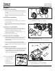
Operator’s Manual Chipper Shredders Air shroud intake/air filter Muffler DEBRIS OFTEN GATHERS IN THIS AREA B A FIGURE 9- Inspect / Rotate Shredding Hammers A. J-Hammer Wear Area B. Access Panel Cooling Fins FIGURE 8 - Clean Debris from Engine Cooling Fins NOTE: Engine air shroud removed from Figure 8 A Clean Debris from Engine & Chipper Service Interval: Before each use and every 100 hours. The engine requires air flow to cool itself and for combustion.
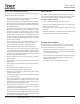
Operator’s Manual Chipper Shredders INSPECT CHIPPING KNIVES Service Interval: Every 25 hours, or as necessary The chipping knives of this unit can be rotated or sharpened to provide a new cutting surface as required. When inspecting the knives be careful to avoid touching the sharpened edges. To inspect the chipping knives: 1. Disconnect the spark plug wire and secure it away from the spark plug. SEE FIGURE 12 A 2. Remove the nuts securing the chipper cone to the front of the chipper.
Operator’s Manual Chipper Shredders TROUBLESHOOTING CHART While normal care and regular maintenance will extend the life of your equipment, prolonged or constant use may eventually require that service be performed to allow it to continue operating properly. The troubleshooting guide below lists the most common problems, their causes, and remedies. See the information on the following pages for instructions on how to perform most of these minor adjustments and service repairs yourself.
Operator’s Manual Chipper Shredders G FIGURE 13 - Gaining access to the knives and hammers REPAIR C C A D G Shredding Hammer Rotation and Replacement The cutting edges of the shredding hammers may eventually wear out requiring rotation of the hammer or replacement if all cutting edges have been dulled. Triangular hammers can be rotated twice after the first edge dulls, then flipped over once and rotated again for a total of 6 edges. J-hammers can be flipped over once for a total of two cutting edges.
Operator’s Manual Chipper Shredders Chipping Knives Sharpening and Replacement The chipping knives should be sharpened or replaced when tree limbs require extra force to feed into the chipper cone. The chipping knives may be sharpened at a 30 degree angle until the distance between the edge of the blade bevel and the mounting hole is less than 1/16” (1.6mm). SEE FIGURE 15. WARNING AMPUTATION HAZARD.
Operator’s Manual Chipper Shredders ILLUSTRATED PARTS BREAKDOWN 21 18 20 11 10 16 13 8 8 10 12 14 25 15 22 19 17 23 24 3 4 9 5 8 6 1 2 7 Check for parts online at www.tazztools.
Operator’s Manual Chipper Shredders ILLUSTRATED PARTS BREAKDOWN ITEM # PART # DESCRIPTION QTY. 1 50175 WASHER 12MM TILLER 2 2 22243 CHIPPER WHEEL 11X 2 2 3 22245 CONE COVER 1 4 21930 WELDMENT CHIPPER CONE 1 5 16400 NUT M8 X 1.25 HSF NYLOC GR8.8 ZN 8 6 22097 COTTER PIN HAIRPIN 2MM X 50MM 2 7 12770 M8 X 1.25 X 40 MM 88 ZN 4 8 20143 WASHER M8 X 16 X 1.6 FLAT ZN 12 9 22093 KICKSTAND CHIPPER 1 10 W1256V0900 NUT M8 X 1.25 HNYLK GR8.8 ZN 8 11 14109 NUT M6 X 1.
Operator’s Manual Chipper Shredders ILLUSTRATED PARTS BREAKDOWN - ENGINE AND ROTOR GROUP (MODEL 18493) 1 2 7 9 8 4 10 3 5 6 ITEM # 1 PART # DESCRIPTION QTY.
Operator’s Manual Chipper Shredders ILLUSTRATED PARTS BREAKDOWN - ENGINE AND ROTOR GROUP (MODEL 22752) 4 1 6 2 7 3 5 8 9 10 24 ITEM # PART # 1 20838 DESCRIPTION WELDMENT PLATE ENGINE QTY. 1 2 21640 WASHER M8 SPRLK ZN 4 3 21959 ASSEMBLY ROTOR HAMMERS AND KNIVES METRIC 1 4 22842 ENGINE HRZ 1 IN SHAFT 10 HP VPR R300 1 5 22860 SPACER 10.31MM IDX 25.4 MM ODX 35.9 MM LG 1 6 23193 SPACER ENGINE R300 TAZZ 90MM C TO C 1 7 23196 BOLT M8 X 1.25 X 55 HHCS GR8.
Operator’s Manual Chipper Shredders ILLUSTRATED PARTS BREAKDOWN - ROTOR GROUP 6 1 7 4 9 2 5 8 13 11 13 2 11 10 8 12 3 ITEM # PART # DESCRIPTION QTY. 1 22668 ASSEMBLY ROTOR KIT 1 2 21958 SPACER 10.1 MM ID X 13 MM ODX 31.242LG 4 3 22669 HAMMER TRIANGULAR 5MM THICK 1 4 22166 SPACER 13.00 ID X 19.050 OD X 18.745 LG 4 5 22670 ASSEMBLY J HAMMER KIT 1 6 21962 KNIFE CHIPPER 76.
Operator’s Manual Chipper Shredders ILLUSTRATED PARTS BREAKDOWN - CHIPPER HOUSING GROUP 9 10 10 11 14 2 7 1 4 8 4 7 13 6 6 5 5 3 *Item shown for illustrative purposes only. 26 12 ITEM # PART # DESCRIPTION QTY. 1 20812 WELDMENT HOUSING ROTOR 1 2 22666 ASSEMBLY BAG CONNECTOR KIT 1 3 22650 COVER ROTOR HOUSING GREEN PANTONE 361 1 4 13599 NUT M6 X 1.0 HHFNYLK GR8.8 ZN 16 5 21640 WASHER M8 SPRING LOCK ZINC 6 6 3241 BOLT M8 X 1.25 12 HHCS GR8.
Operator’s Manual Chipper Shredders ILLUSTRATED PARTS BREAKDOWN - HOPPER GROUP 3 4 7 6 1 ITEM # PART # DESCRIPTION QTY. 1 22667 ASSEMBLY DAMPER KIT 1 2 22026 PLATE NUT M6 1 3 67089 BOLT M6 X 1.0 X 16 HH GR8.8 ZN 8 4 18130 WASHER M6 X 1.5 SPRLK ZN 8 5 14109 NUT M6 X 1.0 HHFNYLK GR8.8 ZN 4 6 22557 WELDMENT CHIPPER HOPPER 1 7 22115 BADGE TAZZ BRANDING 1 8* --- CHIPPER HOUSING GROUP --- 2 5 8 *Item shown for illustrative purposes only. Check for parts online at www.
Operator’s Manual Chipper Shredders ILLUSTRATED PARTS BREAKDOWN - VACUUM KIT (OPTIONAL ACCESSORY) MODEL NO. 22518 1 2 3 13 9 4 8 10 7 5 11 12 6 28 ITEM # PART # DESCRIPTION QTY. 1 1021100 ADAPTER 4IN VAC COL HOSE 1 2 1023100 COUPLER VAC COL HOSE TO ADAPTER 2C 3 1 3 1025100 CAP PLUG 4IN VOL HOSE 2C HOSE 2C 3C 5C 1 4 1035100 HOSE VAC COL 4.
Operator’s Manual Chipper Shredders ILLUSTRATED PARTS BREAKDOWN - TOW BAR KIT (OPTIONAL ACCESSORY) MODEL NO. 1692327 3 4 2 5 7 8 9 6 1 ITEM # PART # DESCRIPTION QTY. 1 1713352 BENT ARM ASSEMBLY, TOW BAR 1 2 1713414 ROD ASSEMBLY-TOW VAR SWING ARM 1 3 1713357 ROD HOLDER ASSY-TOW BAR 1 4 1925205 BOLT 5/16-18 5/8 HHCS GR5 1 5 1423B BOLT 5/16-18 X 2 HHCS GR5 BLK ZN 1 6 1919438 NUT 5/16-18 NYLOCK BLK ZN 1 7 1710726 PIN-CLEVIS .308DIAX1.500LG .
Operator’s Manual Chipper Shredders WARRANTY TERMS AND CONDITIONS Limited 5 Year Chipper Shredder Warranty Ardisam, Inc. (Ardisam) warrants this chipper shredder under a five-year limited warranty to be free from defects in the material or workmanship or both for a period not exceeding sixty consecutive months from the date of original purchase by the first retail consumer or first commercial end user. This warranty does not apply to the engine mounted on the product.
Operator’s Manual Chipper Shredders NOTES Check for parts online at www.tazztools.
Tazz™, Division of Ardisam, Inc. 1160 8th Avenue, PO Box 666 Cumberland, WI 54829 800-345-6007 | Fax 715-822-2223 Email: info@tazztools.com All weights, specifications and features are approximate and are subject to change without notice. Due to continuous product improvements, product images may not be exact. Items used for props not included. Some assembly may be required. Check for parts online at www.tazztools.