
Instructions / Assembly

Johnson Controls Unitary Products 035-22285-002-B-0914
ACCESSORY KIT INSTALLATION MANUAL
IGNITION CONTROL P/N S1-33103010000
FOR MODELS: ALL SINGLE-STAGE 115VAC MODELS WITH HOT SURFACE IGNITION (HSI)
GENERAL INFORMATION
This part is a direct replacement for part numbers
S1-03109167000, S1-03101933000, S1-03101267000,
S1-03101267001, S1-03100662000, S1-03101250000,
S1-03101266000, S1-03101284000, S1-03101973000
and S1-03101972000, 265901, 265902, & 539617.
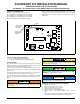
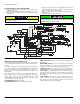
Figure 1 shows the basic board layout and Figure 2 shows the general
component and safety circuit connections (Refer to the electrical wire
diagram for the furnace being serviced for circuit connections specific to
that model).
KIT S1-33103010000 INCLUDES
1. Ignition control board P/N S1-03103010000
2. Accessory Kit Installation Manual P/N 035-22285-002
INSTALLATION
The required number of steps to remove the failed ignition control and
install the new ignition control will vary depending on the furnace model.
However the wire connections will remain the same.
Some models (certain upflow 90% models) will require that the sheet
metal control box be replaced. The existing door switch and transformer
will be re-used.
Some models (BGU Series) will require that new holes be drilled in the
existing control box and that the transformer be relocated.
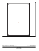
Some models will need new mounting holes to be drilled in the existing
panel. Use the drill template on the last page of these instructions as a
guide.
REMOVAL OF FAILED IGNITION CONTROL
1. Turn off electrical power.
2. Remove furnace blower access panel.
3. Remove electrical box cover, if required.
4. Label all wires prior to disconnection.
5. Disconnect all wires to failed ignition control.
6. Remove screws or pegs fastening ignition control to electrical
panel.
7. Fasten hole template, included with this installation instruction, to
electrical panel and drill new mounting holes. (If required).
FIGURE 1: Furnace Control Board
PARK
PARK
HI COOL
HEAT
EAC-H
L1
XFMR
NEUTRALS
HUM
TWIN
60
90
120
180
BLOWER
OFF
DELAY
Y/Y2
W
R
G
C
Y1
LO COOL
CONT
FAN
SPEED
LO COOL
HEAT
HI COOL
FAN OFF
ADJUSTMENT
JUMPER
CONTINUOUS
FAN SPEED
JUMPER
A0233-001
LED
Disconnect electrical power to the furnace before installing this con-
trol. Failure to cut power could result in an electrical shock or equip-
ment damage.
Label all wires prior to disconnection when servicing controls. Wiring
errors can cause improper and dangerous furnace operation. Verify
proper operation after servicing.
If power is applied and 9 red flashes immediately occur, check for
correct transformer phasing. Refer to the description for the 9 RED
FLASHES of the LED indicator on page 3.
All wiring must be in accordance with both the National Electric
Code, latest edition, and all local electrical codes.
NOTICE