
Instructions / Assembly

035-22285-002-B-0914
2 Johnson Controls Unitary Products
INSTALLATION OF IGNITION CONTROL
1. Orient the control as close as possible to the orientation of the
board being replaced.
2. Align the plastic mounting feet with the mounting holes in the elec-
tric panel and press on each corner of the control board to seat the
mounting feet.
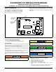
3. Figure 2 shows a typical system wiring diagram, which may vary
slightly depending on the furnace model. Use the wiring diagram
label on the furnace as your primary guide.
4. Check to see that all wire connections were made properly before
applying power.
5. Apply power and test furnace operation.
FURNACE CONTROL DIAGNOSTICS
The furnace has built-in, self-diagnostic capability. If a system problem
occurs, a blinking LED can flash red, green or amber to indicate various
conditions.
The control continuously monitors its own operation and the operation
of the system. If a failure occurs, the LED will indicate the failure code. If
the failure is internal to the control, the light will stay on continuously. In
this case, the entire control should be replaced, as the control is not
field repairable.
Flash sequence codes 1 through 11 are as follows: LED will turn “on”
for 1/4 second and “off” for 1/4 second. This pattern will be repeated the
number of times equal to the code. For example, six flashes “on” will
equal a number 6 fault code. Each separate flash code sequence will
be separated by a 2 second “off” period.
SLOW GREEN FLASH: Normal operation.
SLOW AMBER FLASH: Normal operation with call for heat.
RAPID RED FLASH: Twinning error, incorrect 24V phasing. Check
twinning wiring.
RAPID AMBER FLASH: Flame sense current is below 1.5 microamps.
Check and clean flame sensor. Check for proper gas flow. Verify that
current is greater than 1.5 microamps at flame current test pad.
4 AMBER FLASHES: The control is receiving a “Y” signal from the
thermostat without a “G” signal, indicating improper thermostat wiring.
1 RED FLASH: This indicates that flame was sensed when there was
not a call for heat. The control turns on both the inducer motor and sup-
ply air blower. A gas valve that leaks or is slow closing would typically
cause this fault.
2 RED FLASHES: This indicates that the normally open pressure
switch contacts are stuck in the closed position. The control confirms
these contacts are open at the beginning of each heat cycle. This would
indicate a faulty pressure switch or miswiring.
Apply only enough pressure to seat the mounting foot or the ignition
control may be damaged.
If power is applied and 9 red flashes immediately occur, check for
correct transformer phasing. Refer to the description for the 9 RED
FLASHES of the LED indicator on page 3.
FIGURE 2: Board Layout - Typical System Wiring
A0234-001