Model / Modelo / Modéle Write purchased model number here. Retain these instructions for future use. Escriba aquí el número del modelo comprado. Conserve estas instrucciones para usarlas en el futuro. Inscrivez le numéro de modèle ici. Conservez ces instructions pour consultation.
! REQUIREMENTS FOR SUCCESSFUL INSTALLATION KNOWLEDGE BASE: Framing, Plumbing These instructions include suggestions for rough construction and plumbing installation. Local building codes vary and could supersede those suggestions. If you are not confident in your ability to perform these tasks, contract out those tasks you need help with or use a professional installer. • Confirm that your model will fit in intended location and plumbing fixtures are located where required before beginning installation.
Model / Modelo / Modéle 455000, 455020 Wall Set Parts/ Piezas para la instalación en la pared/ Pièces du contour Hardware Herraje Fixations Models / Modelos / Modéles 455000 RP77596 Models / Modelos / Modéles 455020 RP77588 M5 x 20 mm Pan Head Screw (4) Tornillo de cabeza plana M5 x 20 mm (4) Vis à tête cylindrique bombée M5 x 20 mm (4) Model / Modelo / Modéle 455020 #8 x 3/4” Round Head Screw (4) Tornillo de cabeza redondeada #8 x 3/4” (4) Vis à tête ronde no 8 x 3/4 po (4) M5 Hex Nut (4) Tuerca hexagon
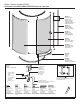
Model / Modelo / Modéle 455000 Enclosure Parts/ PIEZAS DEL RECINTO/ Pièces de l’enceinte RP77574 Wall Jamb (2) & Magnet Jamb Jamba mural (2) y Jamba con imán Jambage mural (2) et jambage aimanté` RP77613 Wall Jamb (2) Jamba mural (2) Jambage mural (2) RP77614 Magnet Jamb Jamba con imán Jambage aimanté RP77657 Door Panel Panel de la puerta Panneau de porte RP77658 Stationary Panel Panel estacionario Panneau fixe RP77587 Gaskets Juntas Joints RP77662 Track Set Piezas del carril Ensemble de glissières RP775
TOOLS AND MATERIALS REQUIRED • Lumber for bracing • Water and drain line materials and fittings • Rags or padding to protect product during bracing NOTE: It is recommended to install insulation. HERRAMIENTAS Y MATERIALES NECESARIOS • Madera de refuerzo • Materiales y accesorios para el agua y la línea de drenaje • Trapos o almohadillas para proteger el producto durante la instalación de la madera para sostener NOTA: Se recomienda instalar el aislamiento.
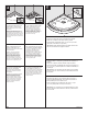
1 2 1/2” Drywall Muro en seco de ½" Panneau de gypse de 1/2 po 3/8” .95 cm Studs Montantes Montants 3/8” Thick Shim Pernos de cuña de 3/8" Cales de 3/8 po d’épaisseur Notch drywall. Shim studs. Haga una rendija en la mampostería seca. Pernos de cuña. Découpez les panneaux de gypse. Placez des cales sur les montants. Place base in position. Check that base is level and square. Trace outline of drain and base on floor and wall. Cut drain access, maximum 5” (12.7 cm) diameter. Install 2” (5.
3 REQUIRED FOR PROPER INSTALLATION ! Entire bottom support must be in contact with a flat level surface as shown. If installation surface is not level, a mortar bed must be applied where the base will be positioned. IF THE SUBFLOOR IS NOT FLAT AND LEVEL REFER TO STEP 4 FOR INSTRUCTIONS. REQUERIDO PARA LA INSTALACIÓN ADECUADA ! Todo el soporte inferior debe estar en contacto con una superficie plana y nivelada.
5 4 IF THE SUBFLOOR IS NOT FLAT AND LEVEL, a mortar bed must be applied where the base will be positioned. Apply a generous amount of mortar that has been mixed to a thick consistency. Use the mortar to fill in low areas. Place the base in the wet mortar, adjust until it is level, and let mortar cure for 24 hours. Proceed to next step. IF THE SUBFLOOR IS FLAT AND LEVEL, apply adhesive on floor and spread using the notched side of the trowel, starting within pencil line.
6 7 Drain Cover Tapa del drenaje Crépine Rubber Seal Sello de goma Garniture de caoutchouc Drain Body Cuerpo del drenaje Corps de renvoi Rubber Gasket Empaque de goma Joint en caoutchouc Paper Gasket Empaque de papel Joint en papier Rubber Seal flush with Pipe Sello de goma al ras con el tubo Garniture de caoutchouc au ras de l’extrémité du tuyau Nut Écrou Tuerca Disassemble drain. Lubricate rubber seal, pipe, and drain. Insert rubber seal and tap down until flush with drain pipe.
2 1 S S APPLY SEALANT to one side of panel only. Position assembled panels onto base. Mark a pencil line on wall around panels. Using adjustable wrench, secure panels with M5 x 20 mm panhead screw, M5 nut, and M5 washers. Using stud finder, mark stud locations for support board installation. Remove panels. Coloque los paneles ensamblados en la base. Marque una línea con un lápiz en la pared alrededor de los paneles. S APLIQUE SELLADOR solo a un lado del panel.
3 X X Y Y Measure and mark location for plumbing fixtures on back of side panel. Using proper size hole saw, cut out plumbing fixture holes from back side of panel. chuck can damage panel. Drill holes from back side ! Drill of side panel. Mida y marque la ubicación de los accesorios de plomería en la parte posterior del panel lateral. Usando una sierra de agujeros de un tamaño adecuado, recorte los agujeros para la grifería desde la parte posterior del panel. portabrocas puede dañar el panel.
4 5 3 1/2" (8.89 cm) b b 6 1/4" (0.64 cm) A a a A S a 1 x 3 x 68” b 1 x 4 x 30” DRY FIT AJUSTE EN SECO INSTALLATION PROVISOIRE A APPLY ADHESIVE to support boards. NOTE: 1 x 3 lumber is actually 3/4” x 2 1/2” 1 x 4 lumber is actually 3/4” x 3 1/2” NOTA: 1 x 3 madera en realidad es 3/4 “x 2 1/2” 1 x 4 madera en realidad es 3/4 “x 3 1/2” NOTE : Les dimensions réelles d’une planche de 1 po x 3 po sont de 3/4 po x 2 1/2 po.
7 8 S Install temporary brace to hold back panel tight against wall while adhesive sets. S APPLY SEALANT to all finished seams. Follow manufacturer’s instructions for sealant dry time before use. Protect surface of wall set and base where it will contact brace. installing finished wall material, do not screw into ! When flanges or product damage will occur. Follow manufacturer’s instructions for adhesive dry time before removing brace.
1 2 1” 2.54(cm) Slots to inside Dentados hacia adentro Rainures du côté intérieur Drill 1/8” holes through screw locations on wall jambs. Position wall jamb 1” in from edge. Use level to ensure they are plumb. Failure to drill pilot holes may cause wall panels to crack. Correct placement of wall jambs is critical to enclosure installation. Secure wall jambs with #8 x 1-1/4” panhead screws. Temporarily secure wall jambs with tape. Mark hole locations on panels. Remove tape and wall jambs.
3 4 Outside of Door El exterior de la puerta Extérieur de la porte Install the gasket into the channel of the door, oriented as shown. On door panel, install a roller block in each corner as shown. Ensure holes are aligned correctly. Instale el empaque en el canal de la puerta, orientado como se muestra. En el panel de la puerta, instale un bloque de rodamientos en cada esquina como se muestra. Asegure que los agujeros están alineados correctamente.
5 6 #8-32 x 3/8” Trusshead Screws Tornillos de cabeza segmentada Vis no 8-32 x 3/8 po à tête bombée #6 x 3/8” Panhead Screws Tornillos de cabeza chanfleada Vis no 6 x 3/8 po à tête plate #6 x 1” Panhead Screws Tornillos de cabeza chanfleada Vis no 6 x 1 po à tête plate M4 x 12 mm Panhead Screws Tornillos de cabeza chanfleada Vis M4 x 12 mm à tête plate Attach top and bottom tracks to stationary panel. Assemble the four roller clips by attaching roller to clip using #8-32 x 3/8” trusshead screws.
7 8 Slide rollers and door into top and bottom track. Attach magnet jamb to top and bottom track using #6 x 1” panhead screws. Secure with M4 x 12mm panhead screw. Deslice los rodamientos y la puerta en el carril superior e inferior. Fije la jamba con el imán en el carril superior y el inferior utilizando tornillos de cabeza chanfleada # 6 x 1”. Fije con tornillos de cabeza chanfleada M4 x 12mm. Introduisez la porte avec les galets dans les glissières supérieure et inférieure.
9 10 Determine desired direction of door opening before continuing. Rotate entire assembly to position door opening as desired. Adjust door and tighten four roller screws using supplied wrench. Door should roll smoothly after all four roller screws have been tightened properly. Position door assembly onto base, inserting ends into wall jambs. Secure with #6 x 3/8” panhead screws. Attach caps to clips as shown.
11 12 Install the bottom door sweep gasket to the bottom of the round door. Install handle with #6 x 3/4” panhead screws as shown. The open side of the handle should face down. Instale el burlete de la puerta inferior en la parte inferior de la puerta redondeada. Instale la manija con un tornillo de cabeza chanfleada # 6 x 3/4” como se muestra. El lado abierto de la manija deberá estar en dirección hacia abajo. Installez le joint racleur de dessous de porte en dessous de la porte ronde.
13 14 S Install gasket plugs into the top and bottom of the tracks on the side opposite of the door. S APPLY SEALANT to all exterior seams where enclosure meets base and walls. Apply to interior metal-to-metal seams and where enclosure meets base and walls. Install plumbing fixtures and fittings following manufacturer’s instructions. Check for leaks at all connections before use. Instale tapones para empaques en el carril superior y en el inferior en el lado opuesto a la puerta.
Model / Modelo / Modéle 455020 1 2 1 3/4” (4.45 cm) 1 1/4” (3.12 cm) Draw pencil lines 1-3/4” over from the edge of the wall and 1-1/4” down from the top of the wall. Use the mounting plate to mark holes. Slide the escutcheons onto the rod and install the mounting plates with the raised side against each rod end using the M3.5 x 12mm panhead screws. Dibuje líneas con lápiz a 1-3/4” del borde de la pared y 1-1/4” hacia abajo desde la parte superior de la pared.
3 4 Hold the rod assembly into position and check that the hole marks line up with the holes in the mounting plates. Adjust one side if needed. Drill pilot holes with a 3/32” drill bit. Sostenga el ensamble de la barra en su posición y fíjese que las marcas del agujero se alinean con los agujeros en las placas de montaje. Ajuste un lado si es necesario. Perfore agujeros piloto con una broca de 3/32” de taladro.
5 6 Mount the rod to the shower walls using #6 x 1 1/4” SS screws. Slide the escutcheons down to the end of the curtain rod. Rotate as needed to align with the rod and cover the mounting plate. The escutcheon should lay flush against the wall. Hang the shower curtain with rings. Instale la barra en las paredes de la regadera/ducha usando tornillos acero inoxidable #6 x 1 1/4”. Deslice las chapas hasta el final de la barra de la cortina.
CARE AND CLEANING For regular cleaning use ONLY mild detergents or warm, soapy water. Use ONLY non-abrasive cloth or sponge. Always rinse surfaces after cleaning. Before cleaning this product with cleaning products, test a small, inconspicuous area. ! Manufacturer does not recommend the use of cleaning products that contain any of the following chemicals. Use of products containing these chemicals can cause the products to crack or discolor and will void the warranty.
LIMITED WARRANTY All parts and finishes of the Shower Kit are warranted to the original consumer purchaser to be free from defects in material and workmanship for the time periods listed below. Delta® recommends using a professional plumber for all installation and repair.