
Use and Care Manual


INTRODUCTION
EN
Your Little Giant condensate pump is designed as an automatic
condensate removal pump for water dripping off an air conditioner
evaporative coil. The pump is controlled by a float/switch mechanism
which turns the pump on when approximately 2-1/4" of water
collects in the tank, and automatically switches off when the tank
drains to approximately 1-1/4".
The Little Giant unit you have purchased is of the highest quality
workmanship and material. It has been engineered to give you long
and reliable service.
Little Giant pumps are carefully packaged, inspected and tested to
ensure safe operation and delivery. When you receive your pump,
examine it carefully to determine that there are no broken or damaged
parts that may have occurred during shipment. If damage has
occurred, make notation and notify the firm that you purchased the
pump from. They will assist you in replacement or repair, if required.
READ INSTRUCTIONS CAREFULLY BEFORE ATTEMPTING
TO INSTALL, OPERATE OR SERVICE THE LITTLE GIANT
PUMP. KNOW THE PUMP APPLICATION, LIMITATIONS AND
POTENTIAL HAZARDS. PROTECT YOURSELF AND OTHERS BY
OBSERVING ALL SAFETY INFORMATION. FAILURE TO COMPLY
WITH INSTRUCTIONS COULD RESULT IN PERSONAL INJURY
AND/OR PROPERTY DAMAGE! RETAIN INSTRUCTIONS FOR
FUTURE REFERENCE. INSTALLATION AND CONNECTIONS
ARE TO BE MADE BY A QUALIFIED PERSON.
SAFETY GUIDELINES
DO NOT USE TO PUMP FLAMMABLE OR EXPLOSIVE FLUIDS
SUCH AS GASOLINE, FUEL OIL, KEROSENE, ETC. DO NOT USE
IN EXPLOSIVE ATMOSPHERES. PUMP SHOULD BE USED WITH
LIQUIDS COMPATIBLE WITH PUMP COMPONENT MATERIALS.
DO NOT HANDLE PUMP WITH WET HANDS OR WHEN STANDING
ON A WET OR DAMP SURFACE, OR IN WATER.THIS PUMP
IS SUPPLIED WITH A GROUNDING CONDUCTOR AND/OR
GROUNDING TYPE ATTACHMENT PLUG. TO REDUCE THE RISK
OF ELECTRICAL SHOCK, BE CERTAIN THAT IT IS CONNECTED
TO A PROPERLY GROUNDED GROUNDING TYPE RECEPTACLE.
IN ANY INSTALLATIONS WHERE PROPERTY DAMAGE AND/OR
PERSONAL INJURY MIGHT RESULT FROM AN INOPERATIVE OR
LEAKING PUMP DUE TO POWER OUTAGES, DISCHARGE LINE
BLOCKAGE, OR ANY OTHER REASON, A BACKUP SYSTEM(S)
AND/OR ALARM SHOULD BE USED.
SUPPORT PUMP AND PIPING WHEN ASSEMBLING AND WHEN
INSTALLED. FAILURE TO DO SO MAY CAUSE PIPING TO BREAK,
PUMP TO FAIL, MOTOR BEARING FAILURES, ETC.
INSTALLATION
1. Before installing pump, allow air conditioner to cycle several
times, collecting condensate in a separate container to help
flush any residual oils that may remain in the system.
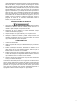
2. Carefully unpack the pump. Remove the cardboard packing
from the motor cover air slots. Carefully slide the packing
away from the pump. This packing is used to prevent switch
movement during shipment (Figure 1).
3. Mounting the pump: the tank has two slots provided to mount
the unit. The slots are located on the ends of the tank (Figure
5). The unit should be mounted either on the side of the air
conditioner unit or nearby wall. Pump must be level and the
inlet must be below the coil drain. Conduit fittings are not
compatible with the plastic pump housing.
4. The pump should not be installed in a manner that will subject
it to splashing or spraying.
5. This pump is not intended for use inside air plenums.
ELECTRICAL CONNECTIONS
1. Shut off electrical power at fuse box before making any
connections. All wiring must comply with local codes.
2. Line voltage: Connect power cord to line voltage specified on
motor and nameplate. Power cord must be connected to a
constant source of power (not a fan or other device that runs
intermittently). If power cord does not have a plug, wiring is as
follows: green (or green/yellow)—ground. Black (or brown)—
line. White (or blue)—neutral.
3. Safety switch: The safety overflow switch should be connected
to a class II low voltage circuit. To control a thermostatic circuit
the COM and NO connections from the safety switch are to be
wired in series with the low voltage thermostat circuit to shut
down the heating/AC circuit. The COM and NC switch contacts
may be used to actuate a low voltage alarm circuit (connected
in series) if the heating/cooling system can not be disrupted.
The safety switch comes from the factory with leads connected
to the COM and NO switch terminals. Typical hook-up of “NC”
circuits would be (Figures 2 & 3).
4. If fused plug is used on 230V units, a 1.0 amp fuse is
recommended.
1
VCMA-10
VCMA-15
VCMA-20
Figure 2
Franklin Electric Co., Inc.
P. O. Box 12010
Oklahoma City, OK 73157-2010
405.947.2511 • Fax: 405.947.8720
www.LittleGiantPump.com
CustomerService-WTS@fele.com
Figure 1