
Installation Guide


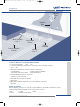
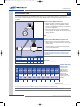
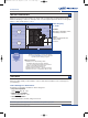
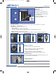
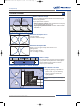
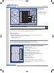
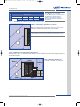
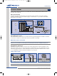
Table Of Contents
- Underground Sprinkler Installation Guide
- Design Section 1 - Why Install?
- Design Section 2 - Check Local Codes
- Design Section 3 - Measure Water Flow
- Design Section 4 - Measure & Draw Property
- Design Section 5 - Select Heads
- Design Section 6 - Head Placement
- Design Section 7 - Creating Watering Zones
- Design Section 8 - Plan Valve Placement
- Design Section 9 - Diagram Pipe Layout
- Design Section 10 - Plan Timer Location
- Design Designing System - Helpful Tools
- Design Layout Graph Paper
- Installation - Helpful Tools
- Installation Section 1 - Installation
- Installation Section 2 - System Layout
- Installation Section 3 - Connect to Water Main
- Installation Section 4 - Backflow Prevention
- Installation Section 5 - Dig Trenches
- Installation Section 6 - Working with Pipe
- Installation Section 7 - Install Main Line
- Installation Section 8 - Install Manifold
- Installation Section 9 - Connect Zones
- Installation Section 10 - Instll Risers & Heads
- Installation Section 11 - Connecting Sprinkler Wire
- Appendix A - Charts
- Appendix A - Selecting the Components
- Appendix A - Parts List

Head to Head Coverage
Proper sprinkler placement allows even watering and
reduces dry patches.
Proper placement requires:
• Head to head coverage: Each sprinkler should spray
to the head beside and across it.
• Equal spacing between heads: Permits uniform water
distribution.
Placement Example: Good
• Good Overlap
• Head to head coverage
Placement Example:
Bad
There is not enough overlap. The center is not
getting water.
• Not enough overlap
• No coverage in center
Nar
row Str
ips
On narrow strips of grass use strip pattern
spray heads and space them evenly apart.
These heads may be used for narrow
strips up to 4 feet wide.
Evenly space strip heads on narrow sections.
Place Heads in Corners
• Begin by placing a sprinkler in
each corner on your drawing.
• Use a compass to draw the
spray pattern.
Note: Use chart 2 on page 20 to obtain spray
distance.
Planning & Design
Sprinkler System Layout & Installation Guide
7
6
PLAN HEAD PLACEMENT
Sidewalk
07WTM003045 53251-01 rE.qxd 3/2/07 2:30 PM Page 7