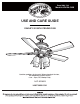
Item #604-748 Model #AC413A-OBB USE AND CARE GUIDE OAKLEY 52 INCH CEILING FAN Questions, problems, missing parts? Before returning to the store, call Hampton Bay Customer Service 8 a.m. - 6 p.m., EST, Monday-Friday 1-877-527-0313 HAMPTONBAY.
Table of Contents Table of Contents .......................................................... 2 Operation ......................................................................15 Pull Chain Operating Instructions .......................................... 15 Reverse Switch Operating Instructions ..................................15 Safety Information ......................................................... 3 Warranty .........................................................................
Safety Information 1. To reduce the risk of electric shock, ensure electricity has been turned off at the circuit breaker or fuse box before beginning. 2. All wiring must be in accordance with the National Electrical Code “ANSI/NFPA 70-1999” and local electrical codes. Electrical installation should be performed by a qualified licensed electrician. 3. WARNING: To reduce the risk of electrical shock or fire, do not use this fan with any solid-state fan speed control device.
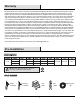
Warranty We warrant the fan motor to be free from defects in workmanship and material present at time of shipment from the factory for a period of lifetime after the date of purchase by the original purchaser. We also warrant that all other fan parts, excluding any glass or acrylic blades, to be free from defects in workmanship and material at the time of shipment from the factory for a period of one year after the date of purchase by the original purchaser.
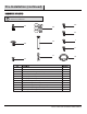
Pre-Installation (continued) HARDWARE INCLUDED NOTE: Hardware shown to actual size unless noted otherwise in the table below.
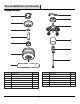
Pre-Installation (continued) PACKAGE CONTENTS H A I B J C D K E L F M G Part Description Quantity Part Description Quantity A Mounting bracket (preassembled) 1 H Blade arm 5 B Canopy 1 I Light kit mounting plate 1 C Canopy bottom cover 1 J Light kit 1 D Hanger ball/downrod assembly 1 K Glass shade 4 E Coupling cover 1 L 13 Watt compact fluorescent bulb 4 F Fan motor assembly 1 M Pull chain and fob 2 G Blade 5 6
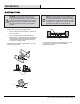
Installation MOUNTING OPTIONS NOTE: You may need a longer downrod to maintain proper blade clearance when installing on a steep, sloped ceiling. The maximum angle allowable is 18° away from horizontal. If the canopy touches the downrod, then remove the decorative canopy bottom cover (C) and turn the canopy (B) 180° before attaching the canopy (B) to the mounting bracket (A).
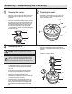
Assembly - Assembling the Fan Body 1 2 Preparing the canopy □ Remove the canopy bottom cover (C) from the canopy (B) by turning the canopy bottom cover (C) counterclockwise. □ Remove the mounting bracket (A) from the canopy (B) by removing the non-slotted mounting bracket screw (CC) from the bottom of the canopy (B) and loosening the slotted mounting bracket screw (CC) a half turn from the screw head. Next, turn the canopy (B) counterclockwise to remove the mounting bracket (A) from the canopy (B).
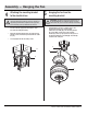
Assembly — Hanging the Fan 4 5 Attaching the mounting bracket to the electrical box Hanging the fan from the mounting bracket WARNING: To reduce the risk of fire, electric shock, or other personal injury, mount the fan only to an outlet box or supporting system marked acceptable for fan support and use the mounting screws provided with the outlet box. □ Pass the 120-volt supply wires through the center hole in the mounting bracket (A).
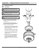
Assembly — Making Electrical Connections 6 Making the electrical connections RR WARNING: To avoid possible electrical shock, be sure electricity is turned off at the main fuse box before wiring. SS WARNING: Check to see that all connections are tight, including ground, and that no bare wire is visible at the wire nuts (except for the ground wire). TT LL AA QQ PP If you feel you do not have enough electrical wiring knowledge or experience, have your fan installed by a licensed electrician.
Assembly — Completing the Fan Body 7 8 Installing the canopy □ WARNING: Make sure the tab on the mounting bracket (A) properly sits in the groove in the hanger ball (D) before attaching the canopy (B) to the mounting bracket (A) by turning the canopy housing until it drops into place. □ Tuck the connections neatly into the ceiling outlet box (LL).
Assembly — Attaching the Fan Blades Removing the rubber packing mounts 9 □ Attaching the blades to the blade arms 10 The fan motor assembly (F) is shipped with rubber packing mounts (UU) to prevent movement during transportation. Remove the five rubber packing mounts (UU) from the fan motor assembly (F) and discard prior to attaching the blade arms. □ Attach the blades (G) to the blade arms (H) using the three blade attachment screws and fiber washers (BB).
Assembly — Installing the Light Kit 12 Attaching the light kit mounting plate to the mounting ring 13 CAUTION: Before starting installation, disconnect the power by turning off the circuit breaker or removing the fuse at the fuse box. Turning power off using the fan switch is not sufficient to prevent electric shock. □ □ Remove one of the three light kit mounting plate screws (II) from the mounting ring (XX), and loosen the other two screws. (Do not remove.
Assembly — Installing the Light Kit (continued) 14 Installing the light bulbs and glass shade CAUTION: Before starting installation, disconnect the power by turning off the circuit breaker or removing the fuse at the fuse box. Turning power off using the fan switch is not sufficient to prevent electric shock. □ Remove the lock ring (KK) from the socket by turning the lock ring (KK) counterclockwise until it unlocks.
Operation PULL CHAIN OPERATING INSTRUCTIONS Install two pull chains and fobs (M) onto the pull chains located in the light kit (J). Turn on the power, and check the operation of the fan. The pull chain controls the fan speed as follows: 1 pull - High, 2 pulls - Medium, 3 pulls - Low, and 4 pulls - Off. Speed settings for warm or cool weather depend on factors such as the room size, ceiling height, and number of fans. To turn the light kit (J) on or off, pull the chain that is attached to the light kit (J).
Care and Cleaning Do □ Do not Check the support connections, brackets, and blade attachments twice a year. Make sure they are secure. Because of the fan’s natural movement, some connections may become loose over time. It is not necessary to remove the fan from the ceiling. □ Clean your fan periodically. Use only a soft brush or lint-free cloth to avoid scratching the finish. The plating is sealed with a lacquer to minimize discoloration or tarnishing.
Troubleshooting WARNING: Make sure the power is off at the electrical panel box before you attempt any repairs. Refer to step 6 “Making the electrical connections” on page 10. Problem The fan will not start. The fan sounds noisy. Solution □ Check the main and branch circuit fuses or breakers. □ Check the line wire connections to the fan and switch wire connections in the switch housing. □ Make sure all motor housing screws are snug.
Service Parts H A AA GG BB HH CC II DD JJ I B J C D K E KK L F EE M FF G Description Part Description A Mounting bracket (preassembled) AA Plastic wire nut B Canopy BB Blade attachment screw and fiber washer C Canopy bottom cover CC Mounting bracket screw (preassembled) D Hanger ball/downrod assembly DD Balance kit E Coupling cover EE Clevis pin (preassembled) Part F Fan motor assembly FF Cotter pin (preassembled) G 5 blades GG Collar setscrew (preassembled) H
Questions, problems, missing parts? Before returning to the store, call Hampton Bay Customer Service 8 a.m. - 6 p.m., EST, Monday-Friday 1-877-527-0313 HAMPTONBAY.COM Retain this manual for future use.