
Instructions / Assembly

©Copyright 2002 Dial Manufacturing, Inc.
4. Electrical Connection:
5. Motor Pulley Adjustment
(Continued)
Disconnect electrical power source prior to making any connections.
115 VAC Motors: 230 VAC Motors:
A. Connect green wire (ground) to
green screw of motor housing.
B. One Speed Motors:
Connect white wire (common) to
white terminal and black wire
(source) to black terminal per
Figure 3.
115 VAC Connection,
One Speed Motor
(Figure 3)
Two Speed Motors:
Connect white wire (common) to
white terminal, black wire (source-
high speed) to black terminal (HI) and
red wire (source-low speed) to red
terminal (LO) per Figure 4. Caution:
Do not
apply voltage across HI to LO.
115 VAC Connection,
Two Speed Motor
(Figure 4)
A. Connect green wire (ground) to
green screw of motor housing.
B. One Speed Motors:
Connect orange wire (first leg of
source) to white terminal and
black wire (second leg of source)
to black terminal Figure 5.
230 VAC Connection,
One Speed Motor
(Figure 5)
Two Speed Motors:
Connect orange wire (first leg of
source) to white terminal, black wire
(second leg of source-high speed) to
black terminal (HI) and red wire
(second leg of source-low speed) to
red terminal (LO) per Figure 6.
Caution: Do not
apply voltage
across HI to LO.
230 VAC Connection,
Two Speed Motors
(Figure 6)
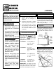
5. Motor Pulley Adjustment:
Important: This motor will work only if (1) correct size pulley is used (see front);
(2) movable half of the adjustable pulley is opened 2-1/2 to 5 turns (see below);
(3) belt tension is correct (see front).
Warning: Disconnect electrical power source prior to working on cooler.
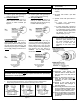
1. Loosen set screw on movable half of pulley with 5/32 Allen wrench.
2. Unscrew movable half of pulley 2-1/2 to 5 full turns from the closed position.
Pulley setting depends on the resistance to air flowing out the cooler.
Several Ducts
Few Ducts
No Ducts
Set Pulley for Air Flow Resistance
(Figure 7)
3. Re-tighten set screw on movable half
of pulley.
4. Re-adjust belt tension (see Belt
Tension).
5. Operate cooler with pad frames in
place.
a. If motor runs continuously,
installation is complete.
b. If motor stops after a period of
time (and restarts later) the motor
is “overloaded” and the movable
half of the adjustable pulley must
be opened 1/2 or more turns.
Repeat steps (1) to (5).
Note: To increase cooler efficiency,
during step 2, use an ammeter to
adjust the pulley diameter until
the motor amperage draw is
equal to, or less than, the
amperage on the motor name
plate.
Set Adjustable Pulley
(Figure 8)
Limited Warranty
(1) Replacement made through your
authorized dealer or retailer within one
year from date of sale with proof of
purchase.
(2) Reason for replacement, purchase date,
failure date, and sales receipt must
accompany all motors returned for
replacement.
(3) Warranty is void if motor has been
abused, altered, water damaged or
improperly installed.
(4) We do not pay the cost of a service call at
the site of installation to diagnose cause
of trouble or the cost of labor or trans-
portation to replace a defective motor.
(5) We are not responsible for any incidental
or consequential damage resulting from
any malfunction unless required to do so
by State Law.