
How to Guide

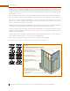

Wall Construction
ENGINEERED WOOD CONSTRUCTION GUIDE
■
FORM NO. B360P
■
© 2011 APA – THE ENGINEERED WOOD ASSOCIATION
■
WWW.APAWOOD.ORG
49
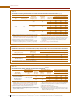
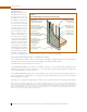
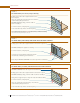
For other fastener types, refer to Table 22. It provides the withdrawal resistance for a number of different fastener types
(smooth-, ring- and screw-shank nails; wood screws and vinyl siding nails). Together with the wind load tables in the
2006 and 2009 International Residential Codes, IRC Tables R301.2(2) and R301.2(3), the attachment schedules for any
combination of siding type, continuous wood structural panel sheathing, design wind speed and exposure can be
determined. See APA Technical Topic: Wood Structural Panels Used as Nailable Sheathing, Form TT-109 for more information
including wind load tables and a sample calculation.
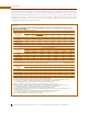
TABLE 22
FASTENER WITHDRAWAL LOADS FOR THE ATTACHMENT OF SIDING TO CONTINUOUS WOOD STRUCTURAL
PANEL WALL SHEATHING
(a)
Ring-Shank Nails
(b)(c)
Withdrawal Loads (lbf)
Wall Sheathing
Performance
Category
Nail Diameter (in.)
0.091 0.094
0.097
0.113 0.120 0.128 0.135 0.1480.099
3/8 31 32 33 38 41 43 46 50
7/16 36 37 38 45 48 51 53 59
15/32 and 1/2 39 40 41 48 51 54 57 63
19/32 and 5/8 49 51 52 61 64 69 73 80
23/32 and 3/4 59 61 63 74 78 83 88 96
Wood Screws
(c)(d)
Withdrawal Loads (lbf)
Wall Sheathing
Performance
Category
Screw Gauge/Diameter (in.)
#6 #7 #8 #9 #10 #12 #14
0.138 0.151 0.164 0.177 0.19 0.216 0.242
3/8 48 52 57 61 66 75 84
7/16 56 61 66 72 77 87 98
15/32 and 1/2 60 65 71 77 82 93 105
19/32 and 5/8 76 83 90 97 104 118 133
23/32 and 3/4 92 100 109 117 126 143 161
Smooth-Shank and Screw-Shank Nails
(c)(e)
Withdrawal Loads (lbf)
Vinyl Siding Nails
(c)(e)(f)
Withdrawal Loads
Wall Sheathing
Performance
Category
Nail Diameter (in.) Nail Diameter (in.)
0.092 0.099 0.113 0.120 0.128 0.131 0.135 0.148 0.122 0.125
3/8 8 8 9 10 11 11 11 12 10 10
7/16 9 10 11 12 13 13 13 14 12 12
15/32 and 1/2 10 10 12 13 13 14 14 16 13 13
19/32 and 5/8 12 13 15 16 17 17 18 20 16 17
23/32 and 3/4 15 16 18 19 21 21 22 24 20 20
(a) Withdrawal capacities are based on the duration of load factor of 1.6 for wind applications. Adjustments for wet service and temperature are
normally not required for attachment to the wood structural panel nailable sheathing.
(b) For ring-shank nails, the withdrawal capacities (W) are based on specific gravities (G) of 0.70 in accordance with APA TT-039 and
W = 1380 G
2.5
D C
D
t, where: W = Withdrawal capacity (lbf), G = Specific Gravity, D = Nail diameter (in.),
C
D
= Duration of load factor (1.6 for wind loads), and t = wood structural panel thickness (in.).
(c) Fasteners shall be long enough to fully penetrate wood structural panel sheathing by at least 1/4 inch.
(d) For wood screws, the withdrawal capacities (W) are based on specific gravities (G) of 0.45 in accordance with APA TT-051 and
W = 2850 G
2
D C
D
t, where: W = Withdrawal capacity (lbf), G = Specific Gravity, D = Nail diameter (in.),
C
D
= Duration of load factor (1.6 for wind loads), and t = wood structural panel thickness (in.).
(e) For smooth-shank, screw-shank, and vinyl siding nails, the withdrawal capacities (W) are based on specific gravities (G) of 0.40 in
accordance with APA TT-039 and
W = 1380 G
2.5
D C
D
t, where: W = Withdrawal capacity (lbf), G = Specific Gravity, D = Nail diameter (in.),
C
D
= Duration of load factor (1.6 for wind loads), and t = wood structural panel thickness (in.).
(f) Vinyl siding nails shall have a head of at least 3/8 inch in diameter.