InvenSense Inc. 1197 Borregas Ave, Sunnyvale, CA 94089 U.S.A. Tel: +1 (408) 988-7339 Fax: +1 (408) 988-8104 Website: www.invensense.com Document Number: PS-MPU-6000A-00 Revision: 3.4 Release Date: 08/19/2013 MPU-6000 and MPU-6050 Product Specification Revision 3.
MPU-6000/MPU-6050 Product Specification Document Number: PS-MPU-6000A-00 Revision: 3.4 Release Date: 08/19/2013 CONTENTS 1 REVISION HISTORY ...................................................................................................................................5 2 PURPOSE AND SCOPE .............................................................................................................................6 3 PRODUCT OVERVIEW ..................................................................
MPU-6000/MPU-6050 Product Specification Document Number: PS-MPU-6000A-00 Revision: 3.4 Release Date: 08/19/2013 7.12 SELF-TEST ........................................................................................................................................27 7.13 MPU-60X0 SOLUTION FOR 9-AXIS SENSOR FUSION USING I C INTERFACE ..........................................28 7.14 MPU-6000 USING SPI INTERFACE ............................................................................................
MPU-6000/MPU-6050 Product Specification 12.2 Document Number: PS-MPU-6000A-00 Revision: 3.4 Release Date: 08/19/2013 QUALIFICATION TEST PLAN ................................................................................................................51 13 ENVIRONMENTAL COMPLIANCE...........................................................................................................
MPU-6000/MPU-6050 Product Specification 1 Document Number: PS-MPU-6000A-00 Revision: 3.4 Release Date: 08/19/2013 Revision History Revision Date Revision Description 11/24/2010 1.0 Initial Release 05/19/2011 2.0 For Rev C parts. Clarified wording in sections (3.2, 5.1, 5.2, 6.1-6.4, 6.6, 6.9, 7, 7.1-7.6, 7.11, 7.12, 7.14, 8, 8.2-8.4, 10.3, 10.4, 11, 12.2) 07/28/2011 2.1 Edited supply current numbers for different modes (section 6.4) 08/05/2011 2.
MPU-6000/MPU-6050 Product Specification 2 Document Number: PS-MPU-6000A-00 Revision: 3.4 Release Date: 08/19/2013 Purpose and Scope This product specification provides advanced information regarding the electrical specification and design related information for the MPU-6000™ and MPU-6050™ MotionTracking™ devices, collectively called the MPU-60X0™ or MPU™. Electrical characteristics are based upon design analysis and simulation results only. Specifications are subject to change without notice.
MPU-6000/MPU-6050 Product Specification 3 Document Number: PS-MPU-6000A-00 Revision: 3.4 Release Date: 08/19/2013 Product Overview 3.1 MPU-60X0 Overview MotionInterface™ is becoming a “must-have” function being adopted by smartphone and tablet manufacturers due to the enormous value it adds to the end user experience.
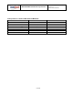
MPU-6000/MPU-6050 Product Specification Document Number: PS-MPU-6000A-00 Revision: 3.4 Release Date: 08/19/2013 Primary Differences between MPU-6000 and MPU-6050 Part / Item VDD VLOGIC Serial Interfaces Supported Pin 8 Pin 9 Pin 23 Pin 24 MPU-6000 2.375V-3.46V n/a 2 I C, SPI /CS AD0/SDO SCL/SCLK SDA/SDI 8 of 52 MPU-6050 2.375V-3.46V 1.
MPU-6000/MPU-6050 Product Specification 4 Document Number: PS-MPU-6000A-00 Revision: 3.
MPU-6000/MPU-6050 Product Specification 5 Document Number: PS-MPU-6000A-00 Revision: 3.4 Release Date: 08/19/2013 Features 5.
MPU-6000/MPU-6050 Product Specification 5.4 5.5 Document Number: PS-MPU-6000A-00 Revision: 3.4 Release Date: 08/19/2013 MEMS structure hermetically sealed and bonded at wafer level RoHS and Green compliant MotionProcessing Internal Digital Motion Processing™ (DMP™) engine supports 3D MotionProcessing and gesture recognition algorithms The MPU-60X0 collects gyroscope and accelerometer data while synchronizing data sampling at a user defined rate.
Document Number: PS-MPU-6000A-00 Revision: 3.4 Release Date: 08/19/2013 MPU-6000/MPU-6050 Product Specification 6 Electrical Characteristics 6.1 Gyroscope Specifications VDD = 2.375V-3.46V, VLOGIC (MPU-6050 only) = 1.8V±5% or VDD, TA = 25°C PARAMETER GYROSCOPE SENSITIVITY Full-Scale Range CONDITIONS MIN MAX ±2 Best fit straight line; 25°C 0.
Document Number: PS-MPU-6000A-00 Revision: 3.4 Release Date: 08/19/2013 MPU-6000/MPU-6050 Product Specification 6.2 Accelerometer Specifications VDD = 2.375V-3.46V, VLOGIC (MPU-6050 only) = 1.8V±5% or VDD, TA = 25°C PARAMETER ACCELEROMETER SENSITIVITY Full-Scale Range ADC Word Length Sensitivity Scale Factor Initial Calibration Tolerance Sensitivity Change vs. Temperature Nonlinearity Cross-Axis Sensitivity ZERO-G OUTPUT Initial Calibration Tolerance Zero-G Level Change vs.
MPU-6000/MPU-6050 Product Specification Document Number: PS-MPU-6000A-00 Revision: 3.4 Release Date: 08/19/2013 6.3 Electrical and Other Common Specifications VDD = 2.375V-3.46V, VLOGIC (MPU-6050 only) = 1.8V±5% or VDD, TA = 25°C PARAMETER TEMPERATURE SENSOR Range Sensitivity Temperature Offset Linearity CONDITIONS MIN Untrimmed 35oC Best fit straight line (-40°C to +85°C) VDD POWER SUPPLY Operating Voltages Normal Operating Current TYP Units -40 to +85 340 -521 °C LSB/ºC LSB ±1 °C 2.
MPU-6000/MPU-6050 Product Specification Document Number: PS-MPU-6000A-00 Revision: 3.4 Release Date: 08/19/2013 6.4 Electrical Specifications, Continued VDD = 2.375V-3.46V, VLOGIC (MPU-6050 only) = 1.
MPU-6000/MPU-6050 Product Specification Document Number: PS-MPU-6000A-00 Revision: 3.4 Release Date: 08/19/2013 6.5 Electrical Specifications, Continued Typical Operating Circuit of Section 7.2, VDD = 2.375V-3.46V, VLOGIC (MPU-6050 only) = 1.
MPU-6000/MPU-6050 Product Specification Document Number: PS-MPU-6000A-00 Revision: 3.4 Release Date: 08/19/2013 6.6 Electrical Specifications, Continued Typical Operating Circuit of Section 7.2, VDD = 2.375V-3.46V, VLOGIC (MPU-6050 only) = 1.
MPU-6000/MPU-6050 Product Specification Document Number: PS-MPU-6000A-00 Revision: 3.4 Release Date: 08/19/2013 2 6.7 I C Timing Characterization Typical Operating Circuit of Section 7.2, VDD = 2.375V-3.46V, VLOGIC (MPU-6050 only) = 1.8V±5% or VDD, TA = 25°C Parameters Conditions I2C TIMING fSCL, SCL Clock Frequency tHD.STA, (Repeated) START Condition Hold Time tLOW, SCL Low Period tHIGH, SCL High Period tSU.STA, Repeated START Condition Setup Time tHD.DAT, SDA Data Hold Time tSU.
MPU-6000/MPU-6050 Product Specification Document Number: PS-MPU-6000A-00 Revision: 3.4 Release Date: 08/19/2013 6.8 SPI Timing Characterization (MPU-6000 only) Typical Operating Circuit of Section 7.2, VDD = 2.375V-3.46V, VLOGIC (MPU-6050 only) = 1.8V±5% or VDD,TA = 25°C, unless otherwise noted. Parameters Conditions Min Typical Max Units 1 MHz SPI TIMING fSCLK, SCLK Clock Frequency tLOW, SCLK Low Period 400 ns tHIGH, SCLK High Period 400 ns tSU.CS, CS Setup Time 8 ns tHD.
MPU-6000/MPU-6050 Product Specification Document Number: PS-MPU-6000A-00 Revision: 3.4 Release Date: 08/19/2013 6.9 Absolute Maximum Ratings Stress above those listed as “Absolute Maximum Ratings” may cause permanent damage to the device. These are stress ratings only and functional operation of the device at these conditions is not implied. Exposure to the absolute maximum ratings conditions for extended periods may affect device reliability. Parameter Rating Supply Voltage, VDD -0.
Document Number: PS-MPU-6000A-00 Revision: 3.4 Release Date: 08/19/2013 MPU-6000/MPU-6050 Product Specification 7 Applications Information 7.1 Pin Out and Signal Description Pin Number MPU6000 MPU6050 1 Y 6 Y 7 Y 8 Y Pin Description Y CLKIN Optional external reference clock input. Connect to GND if unused.
Document Number: PS-MPU-6000A-00 Revision: 3.4 Release Date: 08/19/2013 MPU-6000/MPU-6050 Product Specification 7.2 Typical Operating Circuit 23 C3 2.2nF 22 21 20 SCL SCL / SCLK 24 GND SDA SDA / SDI CLKIN GND 24 23 19 1 18 2 17 3 16 CLKIN C3 2.2nF 22 21 20 19 1 18 2 17 GND MPU-6000 4 GND 3 15 16 MPU-6050 4 15 VDD 5 AUX_DA VDD 14 6 5 13 7 8 9 10 11 6 AUX_DA 12 13 7 C2 0.1µF AUX_CL 14 8 9 10 11 12 C2 0.1µF AUX_CL GND GND C1 0.1µF C1 0.
MPU-6000/MPU-6050 Product Specification Recommended Power-on Procedure All Voltages at 0V 7.4 Document Number: PS-MPU-6000A-00 Revision: 3.4 Release Date: 08/19/2013 Power-Up Sequencing 1. VLOGIC amplitude must always be ≤VDD amplitude TVDDR 2. TVDDR is VDD rise time: Time for VDD to rise from 10% to 90% of its final value 90% VDD 3. TVDDR is ≤100ms 10% 4. TVLGR is VLOGIC rise time: Time for VLOGIC to rise from 10% to 90% of its final value TVLGR 90% 5. TVLGR is ≤3ms VLOGIC 6.
Document Number: PS-MPU-6000A-00 Revision: 3.4 Release Date: 08/19/2013 MPU-6000/MPU-6050 Product Specification 7.
MPU-6000/MPU-6050 Product Specification Document Number: PS-MPU-6000A-00 Revision: 3.4 Release Date: 08/19/2013 7.7 Three-Axis MEMS Gyroscope with 16-bit ADCs and Signal Conditioning The MPU-60X0 consists of three independent vibratory MEMS rate gyroscopes, which detect rotation about the X-, Y-, and Z- Axes. When the gyros are rotated about any of the sense axes, the Coriolis Effect causes a vibration that is detected by a capacitive pickoff.
MPU-6000/MPU-6050 Product Specification Document Number: PS-MPU-6000A-00 Revision: 3.4 Release Date: 08/19/2013 2 7.11 Auxiliary I C Serial Interface 2 The MPU-60X0 has an auxiliary I C bus for communicating to an off-chip 3-Axis digital output magnetometer or other sensors.
MPU-6000/MPU-6050 Product Specification Document Number: PS-MPU-6000A-00 Revision: 3.4 Release Date: 08/19/2013 7.12 Self-Test Please refer to the MPU-6000/MPU-6050 Register Map and Register Descriptions document for more details on self test. Self-test allows for the testing of the mechanical and electrical portions of the sensors. The self-test for each measurement axis can be activated by means of the gyroscope and accelerometer self-test registers (registers 13 to 16).
MPU-6000/MPU-6050 Product Specification Document Number: PS-MPU-6000A-00 Revision: 3.4 Release Date: 08/19/2013 2 7.13 MPU-60X0 Solution for 9-axis Sensor Fusion Using I C Interface 2 In the figure below, the system processor is an I C master to the MPU-60X0. In addition, the MPU-60X0 is an 2 2 I C master to the optional external compass sensor. The MPU-60X0 has limited capabilities as an I C Master, and depends on the system processor to manage the initial configuration of any auxiliary sensors.
MPU-6000/MPU-6050 Product Specification Document Number: PS-MPU-6000A-00 Revision: 3.4 Release Date: 08/19/2013 7.14 MPU-6000 Using SPI Interface In the figure below, the system processor is an SPI master to the MPU-6000. Pins 8, 9, 23, and 24 are used to support the /CS, SDO, SCLK, and SDI signals for SPI communications.
MPU-6000/MPU-6050 Product Specification Document Number: PS-MPU-6000A-00 Revision: 3.4 Release Date: 08/19/2013 7.15 Internal Clock Generation The MPU-60X0 has a flexible clocking scheme, allowing a variety of internal or external clock sources to be used for the internal synchronous circuitry. This synchronous circuitry includes the signal conditioning and ADCs, the DMP, and various control circuits and registers. An on-chip PLL provides flexibility in the allowable inputs for generating this clock.
MPU-6000/MPU-6050 Product Specification Document Number: PS-MPU-6000A-00 Revision: 3.4 Release Date: 08/19/2013 sources); (2) new data is available to be read (from the FIFO and Data registers); (3) accelerometer event interrupts; and (4) the MPU-60X0 did not receive an acknowledge from an auxiliary sensor on the secondary 2 I C bus. The interrupt status can be read from the Interrupt Status register.
MPU-6000/MPU-6050 Product Specification 8 Document Number: PS-MPU-6000A-00 Revision: 3.4 Release Date: 08/19/2013 Programmable Interrupts The MPU-60X0 has a programmable interrupt system which can generate an interrupt signal on the INT pin. Status flags indicate the source of an interrupt. Interrupt sources may be enabled and disabled individually.
Document Number: PS-MPU-6000A-00 Revision: 3.4 Release Date: 08/19/2013 MPU-6000/MPU-6050 Product Specification 9 Digital Interface 2 9.1 I C and SPI (MPU-6000 only) Serial Interfaces 2 The internal registers and memory of the MPU-6000/MPU-6050 can be accessed using either I C at 400 kHz or SPI at 1MHz (MPU-6000 only). SPI operates in four-wire mode.
MPU-6000/MPU-6050 Product Specification Document Number: PS-MPU-6000A-00 Revision: 3.4 Release Date: 08/19/2013 Additionally, the bus remains busy if a repeated START (Sr) is generated instead of a STOP condition. SDA SCL S P START condition STOP condition START and STOP Conditions Data Format / Acknowledge 2 I C data bytes are defined to be 8-bits long. There is no restriction to the number of bytes transmitted per data transfer.
Document Number: PS-MPU-6000A-00 Revision: 3.4 Release Date: 08/19/2013 MPU-6000/MPU-6050 Product Specification Communications After beginning communications with the START condition (S), the master sends a 7-bit slave address th followed by an 8 bit, the read/write bit. The read/write bit indicates whether the master is receiving data from or is writing to the slave device. Then, the master releases the SDA line and waits for the acknowledge signal (ACK) from the slave device.
MPU-6000/MPU-6050 Product Specification Document Number: PS-MPU-6000A-00 Revision: 3.4 Release Date: 08/19/2013 2 To read the internal MPU-60X0 registers, the master sends a start condition, followed by the I C address and a write bit, and then the register address that is going to be read. Upon receiving the ACK signal from the MPU-60X0, the master transmits a start signal followed by the slave address and read bit. As a result, the MPU-60X0 sends an ACK signal and the data.
MPU-6000/MPU-6050 Product Specification Document Number: PS-MPU-6000A-00 Revision: 3.4 Release Date: 08/19/2013 9.5 SPI Interface (MPU-6000 only) SPI is a 4-wire synchronous serial interface that uses two control lines and two data lines. The MPU-6000 always operates as a Slave device during standard Master-Slave SPI operation. With respect to the Master, the Serial Clock output (SCLK), the Serial Data Output (SDO) and the Serial Data Input (SDI) are shared among the Slave devices.
MPU-6000/MPU-6050 Product Specification Document Number: PS-MPU-6000A-00 Revision: 3.4 Release Date: 08/19/2013 10 Serial Interface Considerations (MPU-6050) 10.1 MPU-6050 Supported Interfaces 2 The MPU-6050 supports I C communications on both its primary (microprocessor) serial interface and its auxiliary interface. 10.2 Logic Levels The MPU-6050’s I/O logic levels are set to be VLOGIC, as shown in the table below. AUX_VDDIO must be set to 0. I/O Logic Levels vs.
MPU-6000/MPU-6050 Product Specification Document Number: PS-MPU-6000A-00 Revision: 3.4 Release Date: 08/19/2013 10.3 Logic Levels Diagram for AUX_VDDIO = 0 2 The figure below depicts a sample circuit with a third party magnetometer attached to the auxiliary I C bus. It shows logic levels and voltage connections for AUX_VDDIO = 0. Note: Actual configuration will depend on the auxiliary sensors used.
MPU-6000/MPU-6050 Product Specification Document Number: PS-MPU-6000A-00 Revision: 3.4 Release Date: 08/19/2013 11 Assembly This section provides general guidelines for assembling InvenSense Micro Electro-Mechanical Systems (MEMS) gyros packaged in Quad Flat No leads package (QFN) surface mount integrated circuits. 11.1 Orientation of Axes The diagram below shows the orientation of the axes of sensitivity and the polarity of rotation. Note the pin 1 identifier (•) in the figure.
MPU-6000/MPU-6050 Product Specification Document Number: PS-MPU-6000A-00 Revision: 3.4 Release Date: 08/19/2013 11.2 Package Dimensions 24 Lead QFN (4x4x0.9) mm NiPdAu Lead-frame finish 24 1 L c 19 18 PIN 1 IDENTIFIER IS A LASER MARKED FEATURE ON TOP CO.3 f E E2 e b 13 L1 6 7 D A1 12 D2 A s On 4 corners lead dimensions s SYMBOLS A A1 b c D D2 E E2 e f (e-b) K L L1 s DIMENSIONS IN MILLIMETERS MIN NOM MAX 0.85 0.90 0.95 0.00 0.02 0.05 0.18 0.25 0.30 --0.20 REF --3.90 4.00 4.10 2.65 2.70 2.
MPU-6000/MPU-6050 Product Specification Document Number: PS-MPU-6000A-00 Revision: 3.4 Release Date: 08/19/2013 11.3 PCB Design Guidelines The Pad Diagram using a JEDEC type extension with solder rising on the outer edge is shown below. The Pad Dimensions Table shows pad sizing (mean dimensions) recommended for the MPU-60X0 product.
MPU-6000/MPU-6050 Product Specification Document Number: PS-MPU-6000A-00 Revision: 3.4 Release Date: 08/19/2013 11.4 Assembly Precautions 11.4.1 Gyroscope Surface Mount Guidelines InvenSense MEMS Gyros sense rate of rotation. In addition, gyroscopes sense mechanical stress coming from the printed circuit board (PCB). This PCB stress can be minimized by adhering to certain design rules: When using MEMS gyroscope components in plastic packages, PCB mounting and assembly can cause package stress.
MPU-6000/MPU-6050 Product Specification Document Number: PS-MPU-6000A-00 Revision: 3.4 Release Date: 08/19/2013 Z Φ Y M MP PUU - 600 60 50 0 Θ Package Gyro & Accel Axes ( ) Relative to PCB Axes ( X ) with Orientation Errors (Θ and Φ) The table below shows the cross-axis sensitivity as a percentage of the gyroscope or accelerometer’s sensitivity for a given orientation error, respectively. Cross-Axis Sensitivity vs.
MPU-6000/MPU-6050 Product Specification Document Number: PS-MPU-6000A-00 Revision: 3.4 Release Date: 08/19/2013 Store ESD sensitive devices in ESD safe containers until ready for use. The Tape-and-Reel moisturesealed bag is an ESD approved barrier. The best practice is to keep the units in the original moisture sealed bags until ready for assembly. Restrict all device handling to ESD protected work areas that measure less than 200V static charge.
MPU-6000/MPU-6050 Product Specification Document Number: PS-MPU-6000A-00 Revision: 3.4 Release Date: 08/19/2013 Temperature Set Points Corresponding to Reflow Profile Above CONSTRAINTS Step Setting Temp (°C) Time (sec) Max.
MPU-6000/MPU-6050 Product Specification Document Number: PS-MPU-6000A-00 Revision: 3.4 Release Date: 08/19/2013 11.7 Tape & Reel Specification Tape Dimensions Reel Outline Drawing Reel Dimensions and Package Size PACKAGE REEL (mm) SIZE L V W Z 4x4 330 102 12.8 2.
MPU-6000/MPU-6050 Product Specification Package Orientation Document Number: PS-MPU-6000A-00 Revision: 3.
MPU-6000/MPU-6050 Product Specification Document Number: PS-MPU-6000A-00 Revision: 3.4 Release Date: 08/19/2013 11.
MPU-6000/MPU-6050 Product Specification 11.10 Representative Shipping Carton Label 50 of 52 Document Number: PS-MPU-6000A-00 Revision: 3.
MPU-6000/MPU-6050 Product Specification Document Number: PS-MPU-6000A-00 Revision: 3.4 Release Date: 08/19/2013 12 Reliability 12.1 Qualification Test Policy InvenSense’s products complete a Qualification Test Plan before being released to production. The Qualification Test Plan for the MPU-60X0 followed the JESD47I Standards, “Stress-Test-Driven Qualification of Integrated Circuits,” with the individual tests described below. 12.
MPU-6000/MPU-6050 Product Specification Document Number: PS-MPU-6000A-00 Revision: 3.4 Release Date: 08/19/2013 13 Environmental Compliance The MPU-6000/MPU-6050 is RoHS and Green compliant. The MPU-6000/MPU-6050 is in full environmental compliance as evidenced in report HS-MPU-6000, Materials Declaration Data Sheet. Environmental Declaration Disclaimer: InvenSense believes this environmental information to be correct but cannot guarantee accuracy or completeness.