
Data Sheet
MPU-6000/MPU-6050 Product Specification
Document Number: PS-MPU-6000A-00
Revision: 3.4
Release Date: 08/19/2013
26 of 52
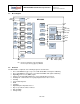
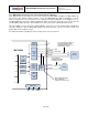
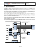
7.11 Auxiliary I
2
C Serial Interface
The MPU-60X0 has an auxiliary I
2
C bus for communicating to an off-chip 3-Axis digital output magnetometer
or other sensors. This bus has two operating modes:
I
2
C Master Mode: The MPU-60X0 acts as a master to any external sensors connected to the
auxiliary I
2
C bus
Pass-Through Mode: The MPU-60X0 directly connects the primary and auxiliary I
2
C buses together,
allowing the system processor to directly communicate with any external sensors.
Auxiliary I
2
C Bus Modes of Operation:
I
2
C Master Mode: Allows the MPU-60X0 to directly access the data registers of external digital
sensors, such as a magnetometer. In this mode, the MPU-60X0 directly obtains data from auxiliary
sensors, allowing the on-chip DMP to generate sensor fusion data without intervention from the
system applications processor.
For example, In I
2
C Master mode, the MPU-60X0 can be configured to perform burst reads,
returning the following data from a magnetometer:
X magnetometer data (2 bytes)
Y magnetometer data (2 bytes)
Z magnetometer data (2 bytes)
The I
2
C Master can be configured to read up to 24 bytes from up to 4 auxiliary sensors. A fifth sensor
can be configured to work single byte read/write mode.
Pass-Through Mode: Allows an external system processor to act as master and directly
communicate to the external sensors connected to the auxiliary I
2
C bus pins (AUX_DA and
AUX_CL). In this mode, the auxiliary I
2
C bus control logic (3
rd
party sensor interface block) of the
MPU-60X0 is disabled, and the auxiliary I
2
C pins AUX_DA and AUX_CL (Pins 6 and 7) are
connected to the main I
2
C bus (Pins 23 and 24) through analog switches.
Pass-Through Mode is useful for configuring the external sensors, or for keeping the MPU-60X0 in a
low-power mode when only the external sensors are used.
In Pass-Through Mode the system processor can still access MPU-60X0 data through the I
2
C
interface.
Auxiliary I
2
C Bus IO Logic Levels
MPU-6000: The logic level of the auxiliary I
2
C bus is VDD
MPU-6050: The logic level of the auxiliary I
2
C bus can be programmed to be either VDD or VLOGIC
For further information regarding the MPU-6050’s logic levels, please refer to Section 10.2.