
Data Sheet

MPU-6000/MPU-6050 Product Specification
Document Number: PS-MPU-6000A-00
Revision: 3.4
Release Date: 08/19/2013
30 of 52
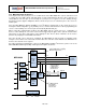
7.15 Internal Clock Generation
The MPU-60X0 has a flexible clocking scheme, allowing a variety of internal or external clock sources to be
used for the internal synchronous circuitry. This synchronous circuitry includes the signal conditioning and
ADCs, the DMP, and various control circuits and registers. An on-chip PLL provides flexibility in the
allowable inputs for generating this clock.
Allowable internal sources for generating the internal clock are:
An internal relaxation oscillator
Any of the X, Y, or Z gyros (MEMS oscillators with a variation of ±1% over temperature)
Allowable external clocking sources are:
32.768kHz square wave
19.2MHz square wave
Selection of the source for generating the internal synchronous clock depends on the availability of external
sources and the requirements for power consumption and clock accuracy. These requirements will most
likely vary by mode of operation. For example, in one mode, where the biggest concern is power
consumption, the user may wish to operate the Digital Motion Processor of the MPU-60X0 to process
accelerometer data, while keeping the gyros off. In this case, the internal relaxation oscillator is a good clock
choice. However, in another mode, where the gyros are active, selecting the gyros as the clock source
provides for a more accurate clock source.
Clock accuracy is important, since timing errors directly affect the distance and angle calculations performed
by the Digital Motion Processor (and by extension, by any processor).
There are also start-up conditions to consider. When the MPU-60X0 first starts up, the device uses its
internal clock until programmed to operate from another source. This allows the user, for example, to wait
for the MEMS oscillators to stabilize before they are selected as the clock source.
7.16 Sensor Data Registers
The sensor data registers contain the latest gyro, accelerometer, auxiliary sensor, and temperature
measurement data. They are read-only registers, and are accessed via the serial interface. Data from these
registers may be read anytime. However, the interrupt function may be used to determine when new data is
available.
For a table of interrupt sources please refer to Section 8.
7.17 FIFO
The MPU-60X0 contains a 1024-byte FIFO register that is accessible via the Serial Interface. The FIFO
configuration register determines which data is written into the FIFO. Possible choices include gyro data,
accelerometer data, temperature readings, auxiliary sensor readings, and FSYNC input. A FIFO counter
keeps track of how many bytes of valid data are contained in the FIFO. The FIFO register supports burst
reads. The interrupt function may be used to determine when new data is available.
For further information regarding the FIFO, please refer to the MPU-6000/MPU-6050 Register Map and
Register Descriptions document.
7.18 Interrupts
Interrupt functionality is configured via the Interrupt Configuration register. Items that are configurable include
the INT pin configuration, the interrupt latching and clearing method, and triggers for the interrupt. Items that
can trigger an interrupt are (1) Clock generator locked to new reference oscillator (used when switching clock