
Data Sheet

MPU-6000/MPU-6050 Product Specification
Document Number: PS-MPU-6000A-00
Revision: 3.4
Release Date: 08/19/2013
31 of 52
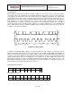
sources); (2) new data is available to be read (from the FIFO and Data registers); (3) accelerometer event
interrupts; and (4) the MPU-60X0 did not receive an acknowledge from an auxiliary sensor on the secondary
I
2
C bus. The interrupt status can be read from the Interrupt Status register.
For further information regarding interrupts, please refer to the MPU-60X0 Register Map and Register
Descriptions document.
For information regarding the MPU-60X0’s accelerometer event interrupts, please refer to Section 8.
7.19 Digital-Output Temperature Sensor
An on-chip temperature sensor and ADC are used to measure the MPU-60X0 die temperature. The
readings from the ADC can be read from the FIFO or the Sensor Data registers.
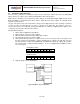
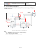
7.20 Bias and LDO
The bias and LDO section generates the internal supply and the reference voltages and currents required by
the MPU-60X0. Its two inputs are an unregulated VDD of 2.375 to 3.46V and a VLOGIC logic reference
supply voltage of 1.71V to VDD (MPU-6050 only). The LDO output is bypassed by a capacitor at REGOUT.
For further details on the capacitor, please refer to the Bill of Materials for External Components (Section
7.3).
7.21 Charge Pump
An on-board charge pump generates the high voltage required for the MEMS oscillators. Its output is
bypassed by a capacitor at CPOUT. For further details on the capacitor, please refer to the Bill of Materials
for External Components (Section 7.3).