
Data Sheet
MPU-6000/MPU-6050 Product Specification
Document Number: PS-MPU-6000A-00
Revision: 3.4
Release Date: 08/19/2013
39 of 52
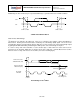
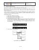
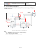
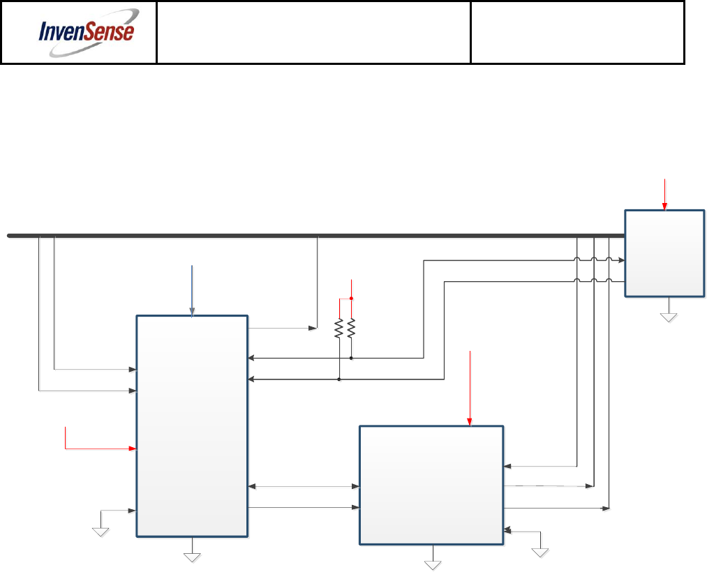
10.3 Logic Levels Diagram for AUX_VDDIO = 0
The figure below depicts a sample circuit with a third party magnetometer attached to the auxiliary I
2
C bus. It
shows logic levels and voltage connections for AUX_VDDIO = 0. Note: Actual configuration will depend on
the auxiliary sensors used.
MPU-6050
3
rd
Party
Magnetometer
SDA
AUX_CL
SCL
AUX_DA
VDD_IO
VDD
SA0
INT 2
INT 1
System
Processor IO
CLKIN
SYSTEM BUS
VLOGIC
VLOGIC
VLOGIC
VDD
VLOGIC
(0V - VLOGIC)
SCL
SDA
INT
FSYNC
VLOGIC
AD0
(0V - VLOGIC)
(0V - VLOGIC)
(0V - VLOGIC)
(0V - VLOGIC)
(0V - VLOGIC)
(0V - VLOGIC)
(0V - VLOGIC)
(0V - VLOGIC)
(0V - VLOGIC)
(0V, VLOGIC)
(0V, VLOGIC)
CS
(0V, VLOGIC)
VDD_IO
I/O Levels and Connections for AUX_VDDIO = 0
Notes:
1. AUX_VDDIO determines the IO voltage levels of AUX_DA and AUX_CL
(0 = set output levels relative to VLOGIC)
2. All other MPU-6050 logic IOs are referenced to VLOGIC.