
Data Sheet

MPU-6000/MPU-6050 Product Specification
Document Number: PS-MPU-6000A-00
Revision: 3.4
Release Date: 08/19/2013
42 of 52
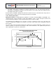
11.3 PCB Design Guidelines
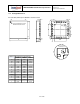
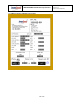
The Pad Diagram using a JEDEC type extension with solder rising on the outer edge is shown below. The
Pad Dimensions Table shows pad sizing (mean dimensions) recommended for the MPU-60X0 product.
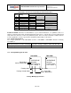
JEDEC type extension with solder rising on outer edge
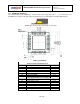
PCB Layout Diagram
SYMBOLS
DIMENSIONS IN MILLIMETERS
NOM
Nominal Package I/O Pad Dimensions
e
Pad Pitch
0.50
b
Pad Width
0.25
L
Pad Length
0.35
L1
Pad Length
0.40
D
Package Width
4.00
E
Package Length
4.00
D2
Exposed Pad Width
2.70
E2
Exposed Pad Length
2.60
I/O Land Design Dimensions (Guidelines )
D3
I/O Pad Extent Width
4.80
E3
I/O Pad Extent Length
4.80
c
Land Width
0.35
Tout
Outward Extension
0.40
Tin
Inward Extension
0.05
L2
Land Length
0.80
L3
Land Length
0.85
PCB Dimensions Table (for PCB Lay-out Diagram)