
Use and Care Manual


7
HAMPTONBAY.COM
Please contact 1-877-527-0313 for further assistance.
Assembly - Standard Ceiling Mount
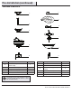
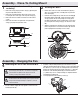
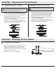
Routing the wires
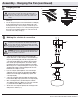
Assembling the fan
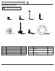
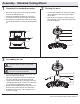
Preparing for standard mounting
□ Loosen, but do not remove, the setscrew (QQ) on the collar
(M) on top of the motor housing (D).
□ Align the holes at the bottom of the downrod (B) with the
holes in the collar (M) on top of the motor housing (D).
□ Carefully insert the hanger pin (CC) through the holes in the
collar (M) and downrod (B). Be careful not to jam the hanger
pin (CC) against the wiring inside the downrod (B).
□ Insert the locking pin (DD) through the hole near the end of
the hanger pin (CC) until it snaps into its locked position.
□ Re-tighten the setscrew (QQ) on the collar (M) on top of
the motor housing (D).
□ Remove the canopy ring (L) from the canopy (C) by turning
the ring to the right until it unlocks.
□ Remove the mounting bracket (A) from the canopy (C) by
loosening the four screws (SS) on the top of the canopy (C).
□ Remove the two non-slotted screws, and loosen the slotted
screws. This will enable you to remove the mounting bracket
(A).
□ Route the wires exiting the top of the fan motor (D) into
the decorative motor collar cover (F) and through the
canopy ring (L).
□ Make sure the slot openings are on top and route the
wires through the canopy (C) and then through the ball/
downrod assembly (B).
2
3
1
C
A
SS
L
C
B
F
D
L
B
F
D
CC
DD
M
QQ
WARNING: Failure to properly install the locking pin (DD)
could result in the fan becoming loose and possibly
falling.
WARNING: Failure to properly install set screw (QQ) could
result in fan loosening and possibly falling.