
User manual


EN
MCA1215 – MCA2440 Connecting the device
55
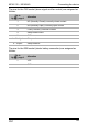
The pins for the CN2 socket (alarm signal and fan control) are assigned as
follows:
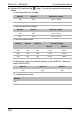
The pins for the ESB socket (starter battery connection) are assigned as
follows:
Pin in
fig. 8, page 6
Allocation
1 NC (Normally Closed): normally closed contact
2 NO (Normally Open): normally open contact
3 COM (Common): common contact
4 Sleep mode control
5GND
4 – 5 bridged Sleep mode on
4 – 5 open Sleep mode off
Pin in
fig. 9, page 6
Allocation
+VCC
–GND