
Installation Guide


INSTALLATION HC-304 CONTINUED
INSTALLATION
NOTE: Built-in wiring compartment allows for: (see chart 1).
1. Drill a 2 1/2" diameter hole in mounting surface.
2. Bring feed wire (Not included) from transformer through
installation hole.
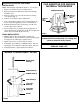
3. Remove housing cover screw (A) and remove housing
c
over (B) (See Fig. 2).
4. Strip 1/4" of insulation from the supply wires.
5. Insert each stripped conductor into the terminal block (C).
Secure in place by tightening screws on terminal block.
6. Reinstall terminal block (C) and housing cover (B), and
secure in place with screw (A).
7. Secure supply wire to housing by placing supply wire on
support (E), then place supply wire holder (D) on supply wire
and secure in place with small screws (F).
FINAL INSTALLATION
1. Making sure that clips are flat against housing and
threaded tube on clip is inserted into channel housing, push
housing into hole until flange is against surface.
2. Tighten clip screws to secure housing to surface.
3. Install lamp. (not included) For 9409 and 9413: 18w max.
Install lamp. (not included) For 9412 and 9416: 20w max.
4. Install desired trim or glass shade (Not Included).
Warning: Use of other manufacturers
components will void warranty, U.L. listing and
create a potential safety hazard.
THREADED TUBE ON CLIP
FROM 1/4"
TO 1"
THICK
FROM 3/4"
TO 1 1/2"
T
HICK
CHANNEL ON
HOUSING
FIGURE 3
DIMMING HALOGEN LAMPS GREATLY
REDUCES LAMP LIFE
FIGURE 2
HOUSING COVER
SCREW (A)
HOUSING COVER (B)
TERMINAL BLOCK (C)
SMALL SCREWS (F)
SUPPLY WIRE
HOLDER (D)
SUPPL
Y WIRE
SUPPOR
T (E)
HOUSING
WIRING COMPARTMENT DETAIL
CLIP DIRECTION FOR VARIOUS
MATERIAL THICKNESSES