B4UB Endurance® B4UB Upright Bike User Manual V.
Table of Contents Table of Contents...................................................................................................... Introduction................................................................................................................ Important Safety Information.............................................................................. Before You Begin....................................................................................................... Assembly..............
Introduction Congratulations!! Thank you for purchasing your new Endurance® Upright Bike. Using state-of-the-art techniques, robust frame structure and superior ergonomic design, Endurance® Upright Bike set a new standard for excellence. The Endurance® Upright Bike can improve your quality of life by keeping you fit and healthy, increasing your energy levels and enhancing your lifestyle.
Important Safety Information Save this Owner’s Manual! Before beginning any fitness program, you should obtain a complete physical examination from your physician. When using exercise equipment, you must always take basic precautions, including the following: m m m m m m m m m m m m m m m Read all instructions before using your Endurance® Upright Bike. These instructions are written to ensure your safety and to protect the unit. DO NOT allow children on or near the equipment.
Before You Begin The Endurance® B4UB is carefully tested and inspected before shipment. We have shipped the unit in several pieces that require assembly. Carefully unpack the unit in a clear area and lay the pieces on the floor near the area where you plan to use the equipment. Remove the packing material. Do not dispose of the packing material until assembly is complete and the unit is working properly. Place the unit on a clean level surface for assembly.
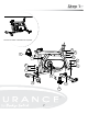
Step 1 NOTE: Some hardware components may be pre-assembled. Be aware of Nylon lock nuts not fully screw onto bolts, they must be tightened with a wrench to ensure proper engagement. 1A. Attach Front Stabilizer (J) to Main Frame (A) using: Two M10x25mm Button Head Cap Screws (#9) Two M10 Lock Washers (#10) Two M10 Flat Washers (#11) 1B. Attach Rear Stabilizer (B) to Main Frame (A) using: Two M10x20mm Button Head Cap Screws (#9) Two M10 Lock Washers (#10) Two M10 Washers (#11) 1D.
在主架(A)上; 在主架(A)上; 2: 2: Step 1 Above shows STEP 1 assembled and completed.
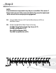
Step 2 NOTE: Some hardware components may be pre-assembled. Be aware of Nylon lock nuts not fully screw onto bolts, they must be tightened with a wrench to ensure proper engagement. 2A. Connect Wire Harness (#15) to the Wire Harness (#18) on the Main Frame. 2B.
垫(19)、平垫(20)、弧垫(21)将把立管(B)锁紧在主架(A)上; Step 2 BB B Above shows STEP 2 assembled and completed.
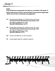
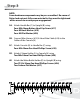
Step 3 NOTE: Some hardware components may be pre-assembled. Be aware of Nylon lock nuts not fully screw onto bolts, they must be tightened with a wrench to ensure proper engagement. 3A. Attach Handle Bar (C) to Upright (B) using: Four M8x16mm Button Head Cap Screw (#17) Four M8 Lock Washer (#19) Four M8 Flat Washer (#20) 3B. Connect Wire Harness (#15) & Heart Rate Cable (#16) to the Cables of the Console (H) 3C. Attach Console (H) to Handle Bar (C) using: Four M5x10mm Pan Head Phillips Screw (#29) 3D.
六角盘头螺钉(17)、弹垫(19)、平垫(20)将把手结合(C)锁紧在把立管(B)上; 2:用十字盘头螺钉( 29)将书报板(L)锁紧在电子表( H)上;用十字盘头自攻螺钉 (26)、平垫(27)将水壶架(K)锁紧在把立管(B)上; 步骤三: 3:先将握把线(16)、感应中继线(15)与电子表(H)相应线连接,然后用 十字盘头螺 1:先将感应中继线(15)从把手结合(C)的表托板下端口穿入,上端口穿出,然后用内 钉(29)将电子表(H)锁紧在 把手结合(C)上。 六角盘头螺钉(17)、弹垫(19)、平垫(20)将把手结合(C)锁紧在把立管(B)上; Step 3 2:用十字盘头螺钉( 29)将书报板(L)锁紧在电子表( H)上;用十字盘头自攻螺钉 (26)、平垫(27)将水壶架(K)锁紧在把立管(B)上; H 3:先将握把线(16)、感应中继线(15)与电子表(H)相应线连接,然后用 十字盘头螺 钉(29)将电子表(H)锁紧在 把手结合(C)上。 L 16 29 H 29 C 15 29 Above shows STEP 3 assembled and completed.
Step 4 NOTE: Some hardware components may be pre-assembled. Be aware of Nylon lock nuts not fully screw onto bolts, they must be tightened with a wrench to ensure proper engagement. 4A. Loosen Threaded Stub Knob (#12) by turning counter-clockwise. Insert Seat Frame (D) into the Main Frame (A). 4B. Attach Adjustment Bracket (E) to Seat Frame (D) using: One T-Bracket (#22) One Bushing (#14) One Knob (#13) 4B.
(14)、限位板(22)将鞍座调节板(E)锁紧在鞍管竖管(D)上。 2.先调整好鞍座调节板(E)的前后距离,然后用梅花柄螺母(13)、隔套 3.先旋松弹销旋钮(12), 然后将 鞍管竖管(D)插入主架(A)的立管孔内,调 (14)、限位板(22)将鞍座调节板(E)锁紧在鞍管竖管(D)上。 整适当高度,对好孔位后,用 弹销旋钮(19)将其锁紧.注意:在运动之前必须确保鞍 3.先旋松弹销旋钮(12), 然后将 鞍管竖管(D)插入主架(A)的立管孔内,调 座(23)锁紧在鞍座调节板( E)上。 整适当高度,对好孔位后,用 弹销旋钮(19)将其锁紧.注意:在运动之前必须确保鞍 座(23)锁紧在鞍座调节板( E)上。 Step 4 Above shows STEP 4 assembled and completed.
SETTING UP B4UB 2 PLACEMENT IN YOUR HOME To make exercise a desirable daily activity for you, the B4UB should be placed in a comfortable and attractive setting. This bike is designed to use minimal floor space and to fit nicely in your gym/home. 2 B Do not place or operate the B4UB outdoors. Do not place the B4UB near water or in high moisture content environment. It is highly recommended to place a dedicated equipment mat beneath your B4UB.
Dimensions 15
Console Overview Take a few moments to review the console Screen layout.
Console Overview CONSOLE DISPLAY Resistance Level The resistance level display is located on the upper left side of the screen . There are 24 resistance Levels to choose from. User Profile The User profile display is located on the upper right side of the screen. There are 5 user profiles can be entered into the program.
Console Overview CONSOLE BUTTONS Quick Program Buttons The Quick Program buttons all the user to launch a program quickly. The programs are MANUAL, PROGRAM, FITNESS, WATT, PERSONAL, HRC and RANDOM. Increase & Decrease Buttons The Increase and Decrease arrow buttons are for adjusting values in both program and setup modes. Quick Start Button Press the Quick Start Button to immediately launch the Quick Start program and bypass data entry.
Console Operation MODES Setup Mode: When Powered on, the console beeps and then goes into setup mode. Sleep Mode: When RPM Signal or Data is not detected for 4 minutes, it will automatically enter Sleep Mode. Pedal again or press any button to start the program again. USER SETUP MODE When entering the program, You have the option of entering your own personal settings (Gender, Age, Height, Weight). 1. In the Setup Mode, hold the Reset Button until it display “U0” on the screen. (Figure #1 & #2) 2.
Console Operation QUICK START PROGRAM This is the quickest way to start a workout. After the console is powered up, Press the Quick Start Button to begin the workout program. In Quick Start Mode, Time will count up from zero and all workout data will start to accrue. Resistance Level can be adjusted by pressing Up or Down Buttons. There are 24 levels of resistance available. PRESET PROGRAMS There are seven Pre-Set Programs (MANUAL, PROGRAM, FITNESS, WATT, PERSONAL, H.R.C., RANDOM) to choose from.
Console Operation PROGRAM This program has a total of 12 different exercise profiles. Exercise profiles (Figure #1021) are shown on page #26. To start the program, 1. In the Setup Mode, Press Increase or Decrease Buttons to choose PROGRAM program and then press Enter Button. 2. Press Increase or Decrease Buttons to choose P1-P12 and then press Enter Button. 3. Press INCREASE or Decrease Buttons to adjust the Level and then press Enter Button. 4.
Console Operation Fat Burn: It is designed to get user’s heart rate fast and maintains it at 65% of your calculated maximum heart rate with slight variation to provide optimal calories burn . (Figure #14 - #15) 上海祺电电子科技有限公司(VISTA CO. LTD.) Page 5 Interval: It is designed to vary the intensity of the workout between low and high resistance to quickly raise and lower the heart rate thru a series of high & low profiles Note: Fitness of a user is shown by Message. (Figure #16 - #18).
Console Operation WATT This program allows the user to adjust Watt value to acheive different resistance level (Figure #6). To Start the program, 1. In the Setup Mode, Press Increase or Decrease Buttons to choose WATT program and then press Enter Button. 2. Press Increase or Decrease Buttons to adjust the Time and then press Enter Button. 3. Press Increase or Decrease Buttons to adjust the Distance and then press Enter Button. 4.
Console Operation H.R.C. Heart rate control programs are designed to automatically change resistance to keep your heart rate at a predetermined level based on the selected Heart Rate program. Each Heart Rate program is designed with a specific goal in mind (Figure #8). To Start the program, 1. In the Setup Mode, Press Increase or Decrease Buttons to choose H.R.C. 2. Press Increase or Decreasen Buttons to choose 55%, 75%, 90% or Tag and then press Enter Button.
Console Operation PRESET PROGRAMS Figure #3 Figure #4 Figure #5 Figure #6 Figure #7 Figure #8 Figure #9 25
Console Operation 12 EXERCISE PROFILE PROGRAMS Figure #10 Figure #11 Figure #12 Figure #13 Figure #14 Figure #15 Figure #16 Figure #19 Figure #17 Figure #20 26 Figure #18 Figure #21
Monitoring Your Heart Rate To obtain the greatest cardiovascular benefits from your exercise workout, it is important to work within your target heart rate zone. The American Heart Association (AHA) defines this target as 60% -75% percent of the Maximum Heart Rate. The Maximum Heart Rate may be roughly calculated by subtracting the user’s age from 220. The Maximum Heart Rate and aerobic capacity naturally decreases as the user ages.
Monitoring Your Heart Rate Fitness Safety The Heart Rate chart indicates average rate zones for different ages. A variety of different factors (including medication, emotional state, temperature and other conditions) can affect the target heart rate zone that is best for you. Your physician or health care professional can help you determine the exercise intensity that is appropriate for your age and condition. (MHR) = Maximum Heart Rate (THR) = Target Heart Rate 220 - Age = Maximum Heart Rate (MHZ) MHZ x .
Chest Strap Operation Your Endurance® Upright bike has the capability to determine Heart Rate with the use of a Heart Rate Chest Strap. A Heart Rate Chest Strap can be purchased seperately. In all Heart Rate Control programs, the console only accepts the heart rate signal from the chest strap transmitter while the pulse grip heart rate function is disabled. The requirement to wear the chest strap is due to the superior accuracy of a chest strap transmitter compared to the pulse grip sensors.
General Maintenace Your Endurance® B4UB Exercise Bike has been manufactured to withstand many hours of use with minimal maintenance. Here are some maintenance tips to keep your Endurance® B4UB Exercise Bike running at its best. Cleaning Periodically wipe down your machine with mild, soapy water or a diluted general purpose non-abrasive household cleaner. Cleaner should never be applied directly to any part of the equipment.
Trouble Shooting Guide Symptom Console has no power. Strides/Min or Speed shows 0 Possible Cause Solution Console cable is not connected? Verify that the console cable is connected properly. The console is faulty? Call the Endurance® service number. Computer isn’t receiving a signal from the sensor? The sensor is faulty? The computer is faulty? Check that the sensor magnet is correctly fitted and passes in front of the sensor.
Stretching & Flexibility Flexibility is an important component of physical fitness and needs to be addressed in a resistance training program. The two main purposes for stretching are injury prevention and a faster rate of recovery from exercise. Stretching should be performed in both the warm up and cool down phases of a training session.
Warm Up/Cool Down Exercises Upper Back Cross Arm in Front of Chest MUSCLE(S) AFFECTED: latissimus dorsi and teres major 1. Stand or sit with the right arm slightly flexed (15° to 30°) and adducted across the chest. 2. Grasp the upper arm just above the elbow, placing the left hand on the posterior side of the upper arm. 3. Pull the right arm across the chest (toward the left) with the left hand; hold for 10 seconds. 4. Repeat with the left arm.
Warm Up/Cool Down Exercises Lower Back Semi-Leg Straddle MUSCLE(S) AFFECTED: spinal erectors 1. Sitting, knees flexed 30 to 50 degrees, let the legs totally relax. 2. Point the knees outward; the lateral side of the knees may or may not touch the floor. 3. Lean forward from waist and reach forward with extended arms; hold position for 10 to 15 seconds. 4. Bending and relaxing legs decreases hamstring involvement and increases lower back stretch.
Warm Up/Cool Down Exercises chest/shoulder Straight Arms Behind Back MUSCLE(S) AFFECTED: deltoids and pectoralis major 1. 2. 3. 4. 5. Standing, place both arms behind back. Interlock fingers with palms facing each other. Straighten arms fully. Slowly raise the straight arms; hold for 10 to 15 seconds. Keep head upright and neck relaxed.
Warm Up/Cool Down Exercises ANTERIOR OF THIGH AND HIP FLEXOR Side Quadricep Stretch MUSCLE(S) AFFECTED: quadriceps and iliopsoas 1. 2. 3. 4. 5. Lie on left side with both legs straight. Place left forearm flat on floor and upper arm perpendicular to floor. Place left forearm at 45° angle with torso. Flex right leg with heel of right foot moving toward buttocks. Grasp front of ankle with right hand and pull toward buttocks. WARNING: Do not pull on ankle so hard that pain or discomfort is felt in knee. 6.
Warm Up/Cool Down Exercises POSTERIOR OF THIGH Semistraddle (Figure Four) MUSCLE(S) AFFECTED: gastrocnemius, hamstrings and spinal erectors 1. Sit with the upper body nearly vertical and legs straight. 2. Place sole of left foot on left side of right knee. The lateral side of left leg should be resting on the floor. 3. Lean forward from the waist and grasp toes with right hand and slightly pull toes toward the upper body as the chest is also pulled toward right leg; hold for 10 seconds. 4.
Warm Up/Cool Down Exercises groin Butterfly MUSCLE(S) AFFECTED: adductors and sartorius 1. Sitting with the upper body nearly vertical and legs straight, flex both knees as the soles of the feet come together. 2. Pull feet toward body. 3. Place hands on feet and elbows on legs. 4. Pull torso slightly forward as elbows push legs down; hold for 10 to 15 seconds. Stretching the groin POSTERIOR OF LOWER LEG Bent-Over Toe Raise MUSCLE(S) AFFECTED: gastrocnemius and soleus 1. 2. 3. 4.
Warm Up/Cool Down Exercises hips Forward Lunge (Fencer) MUSCLE(S) AFFECTED: iliopsoas, rectus femoris 1. 1. Standing, take a long step forward (as with the lunge) with the right leg and flex the right knee until it is directly over the right foot. 2. Keep right foot flat on floor. 3. Keep back leg straight. 4. Keep back foot pointed in same direction as front foot; it is not necessary to have heel on floor. 5. Keep torso upright and rest hands on hips or front leg. 6.
Parts & Hardware List Part# Description QTY A MAIN FRAME 1 B UPRIGHT 1 C HANDLE BAR 1 D SEAT FRAME 1 E ADJUSTMENT BRACKET 1 F LEFT PEDAL 1 G RIGHT PEDAL 1 H CONSOLE 1 R REAR STABILIZER 1 J FRONT STABILIZER 1 K WATER BOTTLE HOLDER 1 L L SHAPE HOLDER 1 1 LEFT CRANK 1 2 RIGHT CRANK 1 3 FOOT CAP 4 4 TRANSPORT WHEEL 2 5 LEVELER 5 6 M10 HEX LOCK NUT 5 7 M10x45mm BUTTON HEAD CAP SCREW 2 8 M10 NYLON LOCK NUT 3 9 M10x25mm BUTTON HEAD CAP SCR
Parts & Hardware List Part# Description QTY 13 KNOB 1 14 BUSHING 1 15 WIRE HARNESS 1 16 HEART RATE CABLE 2 17 M8x16mm BUTTON HEAD CAP SCREW 13 18 WIRE HARNESS 1 19 M8 LOCK WASHER 11 20 M8 FLAT WASHER 8 21 M8 CURVED WASHER 2 22 T-BRACKET 1 23 SEAT 1 24 M8 FLAT WASHER 3 25 M8 NYLON LOCK NUT 3 26 ST4.2x18mm PAN HEAD PHILLIPS SCREW 13 27 9x4mm FLAT WASHER 2 28 POWER ADAPTOR 1 29 M5x10mm PAN HEAD PHILLIPS SCREW 10 30 PLUG 2 31 M10x1.
Parts & Hardware List Part# Description QTY 37 SERVO 1 38 BELT WHEEL 1 39 AXLE 1 40 M8 NYLON LOCK NUT 4 41 TENSION ROLLER 1 42 L BRACKET 1 43 TENSION CABLE 1 44 POWER CORD 1 45 M10x20mm BUTTON HEAD CAP SCREW 1 46 SPRING 1 47 ADJUSTMENT SCREW 1 48 M6 HEX NUT 1 49 BELT 1 50 M10x1.
NOTE 43
Exploded Drawing H 16 29 L C 15 19 17 20 23 22 E 13 25 24 K 27 26 B 20 14 17 19 17 21 12 D 18 A F 11 10 10 4 2 3 9 10 11 1 9 29 5 6 R 3 5 5 G 44 J 28 9 11 8 6 5 3 7 4
Exploded Drawing 30 1 31 32 34 36 35 43 26 18 26 37 44 35 34 8 42 33 45 51 29 50 41 11 40 19 46 38 47 48 17 39 40 26 52 49 26 53 50 29 51 26 2 26 31 26 30 45
Serial Number is Located on the Frame Model Name : B4UB Purchase Date: _______________________________ Serial Number: _______________________________ Customer Tech Support Hotline Toll Free: 1-800-556-3113 Phone: 1-708-427-3555 Fax: 1-708-427-3556 Hours: M-F 8:30-5:00 CST E-Mail: service@bodysolid.