BP7471-2 4TH AVE 2/4/14 9:43 AM Page 1 READ AND SAVE THESE INSTRUCTIONS 4TH AVENUE™ 60” Ceiling Fan Owner's Manual Model Numbers CF766BS00 - Brushed Steel CF766SW00 - with Chocolate Blades Satin White with Satin White Blades CF766ORB00 - Oil Rubbed Bronze with Oil Rubbed Bronze Blades CF766VS00 - Vintage Steel with Riverwash Blades CF766SBS00 - Brushed Steel with Brushed Steel Blades Net Weight: 28.9 Lbs.
BP7471-2 4TH AVE 2/4/14 9:43 AM Page 2 Table of Contents Section Page 7. Using Your Ceiling Fan . . . . . . . . . . . . . . . . . . . . . . .11-12 8. Maintenance . . . . . . . . . . . . . . . . . . . . . . . . . . . . . . . . . .13 9. Accessories . . . . . . . . . . . . . . . . . . . . . . . . . . . . . . . . . . .13 10. Energy Efficient Use of Ceiling Fans . . . . . . . . . . . . . .13 11. Trouble Shooting . . . . . . . . . . . . . . . . . . . . . . . . . . . . . .14 10. Repair Parts . . . . . . . . .
BP7471-2 4TH AVE 2/4/14 9:43 AM Page 3 1. Unpacking Instructions ! PACKAGE CONTENTS WARNING Do not install or use fan if any part is damaged or missing. Call Toll-Free: Part A B C D E F G H I J K L M N 1-800-654-3545 ! Description WARNING This product is designed to use only those parts supplied with this product and/or any accessories designated specifically for use with this product by Emerson Electric Co.
BP7471-2 4TH AVE 2/4/14 9:43 AM Page 4 1. Unpacking Instructions (continued) This Manual Is Designed to Make it as Easy as Possible for You to Assemble, Install, Operate and Maintain Your Ceiling Fan Installed Wire Length Up to 50 ft. 50-100 ft. Tools Needed for Assembly One Phillips head screwdriver One stepladder One wire stripper ! Wire Size A.W.G. 14 12 WARNING Before assembling your ceiling fan, refer to section on proper method of wiring your fan (page 9).
BP7471-2 4TH AVE 2/4/14 9:43 AM Page 5 3. Ceiling Fan Assembly 1. Position the flange marked “THIS SIDE UP”on top of the blade marked “THIS SIDE UP” (Figure 1). #10-32 x 1/4" WASHER HEAD SCREW (3 per blade/flange) 2. Place a decorative nut through the underside of the blade and attach the blade flange to the fan blade using the #10-32 x 1/4” washer head screw. Use three screws with lockwashers per blade assembly (Figure 1). THIS SIDE UP 3.
BP7471-2 4TH AVE 2/4/14 9:43 AM Page 6 3. Ceiling Fan Assembly (continued) 8. Place the upper housing plate so that the two notched areas align with the two studs on the motor coupler. Aligning the six screw holes of the upper housing plate onto the motor hub. Firmly attach the upper housing to the motor hub/upper housing plate by using the six #8-32 x 1/2” pan head screws with lockwashers (supplied) (Figure 4). 9.
BP7471-2 4TH AVE 2/4/14 9:43 AM Page 7 3. Ceiling Fan Assembly (continued) 14. The fan comes with blue, black and white leads that are 80-inches long. Before installing the fan, measure up approximately 6 to 9-inches above top of hanger ball/downrod assembly. Cut off excess leads and strip back insulation 1/2-inch from end of leads. SWITCH ADAPTER SCREW (3) LOWER HOUSING 15.
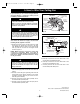
BP7471-2 4TH AVE 2/4/14 9:43 AM Page 8 4. How to Hang Your Ceiling Fan ! CEILING WARNING The fan must be hung with at least 7' of clearance from floor to blades (Figure 11). ! AT LEAST 7' WARNING The outlet box and joist must be securely mounted and capable of supporting at least 50 lbs. Use only a U.L. outlet box listed as “Acceptable for Fan Support of 22.7 kg. (50 lbs.) or less”.
BP7471-2 4TH AVE 2/4/14 9:43 AM Page 9 5. How to Wire Your Ceiling Fan If you feel that you do not have enough electrical wiring knowledge or experience, have your fan installed by a licensed electrician. SUPPLY BLACK WIRE (HOT) GROUND WIRE WARNING RECEIVER RED WIRE RECEIVER BLUE WIRE 1-1/4" THREADED STUD (2) WARNING RL MO TO TOR N TTOM LIG TO MO TO AC IN L ANTENNA Turning off wall switch is not sufficient.
BP7471-2 4TH AVE 2/4/14 9:43 AM Page 10 6. Installation of Glass Shade 1. Install two 60-watt (maximum) candelabra base light bulbs (included) into the light fitter sockets Figure 16). ! WARNING Over lamping the fan will result in the light bulbs being automatically shut off. Use only 60-watt maximum candelabra light bulbs. Turn off the electricity before replacing the light bulbs. 60-WATT (Max.) CANDELABRA BASE LIGHT BULB (2) 2.
BP7471-2 4TH AVE 2/4/14 9:43 AM Page 11 7. Using Your Ceiling Fan ! WARNING To avoid possible fire or shock, make sure that the electrical wires are completely inside the outlet box and not pinched between the ceiling cover and the ceiling. CEILING COVER 1. Push the wires and connectors up into the outlet box while inserting the receiver fully into the hanger bracket. THREADED STUDS (2) LOCKWASHERS (2) 2 Position the antenna wire on top of the receiver. KNURLED KNOBS (2) Figure 18 3.
BP7471-2 4TH AVE 2/4/14 9:43 AM Page 12 7. Using Your Ceiling Fan (continued) 12. Connect one black wire of wall control to the “hot” wire. Securely connect wires with wire connectors supplied (Figure 21). 13. Connect one black wire of wall switch to the “load” (black) wire in wall box. Securely connect wires with wire connector supplied. 14. Screw wall control into wall box and install decorator style faceplate (included). Leave wall control in “OFF” mode until fan installation is completed.
BP7471-2 4TH AVE 2/4/14 9:43 AM Page 13 8. Maintenance IMPORTANT CARE INSTRUCTIONS for your Ceiling Fan ! WARNING Do not use water when cleaning your ceiling fan. It could damage the motor or the blades and create the possibility of an electrical shock. Periodic cleaning of your new ceiling fan is the only maintenance that is needed. When cleaning, use only a soft brush or lint free cloth to avoid scratching the finish.
BP7471-2 4TH AVE 2/4/14 9:43 AM Page 14 11. Trouble Shooting ! WARNING: FOR YOUR OWN SAFETY TURN OFF POWER AT FUSE BOX OR CIRCUIT BREAKER BEFORE TROUBLE SHOOTING YOUR FAN. TROUBLE 1. Fan will not start. PROBABLE CAUSE SUGGESTED REMEDY 1. Fuse or circuit breaker blown. 1. Check main and branch circuit fuses or circuit breakers. 2. Loose power line connections to the fan, or loose switch wire connections in the switch housing. 2.
BP7471-2 4TH AVE 2/4/14 9:43 AM Page 15 Notes 15 emersonfans.com Please contact 1-800-654-3545 for further assistance ETL Model No.
BP7471-2 4TH AVE 2/4/14 9:43 AM Page 16 12. Repair Parts 4 2 1 3 5 16 17 25 6 7 18 .... OFF ON 10 15 19 11 20 8 9 22 12 THIS SIDE UP 13 THIS SIDE UP 21 23 14 13 24 16 ETL Model No.
BP7471-2 4TH AVE 2/4/14 9:43 AM Page 17 12. Repair Parts Listing Model Numbers Key No.
BP7471-2 4TH AVE 2/4/14 9:43 AM Page 18 Notes 18 ETL Model No.
BP7471-2 4TH AVE 2/4/14 9:43 AM Page 19 Emerson Air Comfort Ceiling Fan Limited Warranty What The Limited Warranty Covers: This limited warranty is offered by Air Comfort Products division of Emerson Electric Co.
BP7471-2 4TH AVE 2/4/14 9:43 AM Page 20 Air Comfort Products DIVISION OF EMERSON ELECTRIC CO. 8100 W. Florissant • St. Louis, MO 63136 Questions, problems, missing parts: Before returning to the store call Emerson Electric Customer Service 8 a.m. - 6 p.m., Eastern, Monday-Friday 1-800-654-3545 www.emersonfans.com Retain this manual for future use. Part No. F40BP74710002 Revision: 140204 Printed in China 02/14 Form No. BP7471-2 ETL Model No.