
Instructions / Assembly


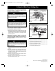


3. Ceiling Fan Assembly
5
emersonfans.com
Please contact 1-800-654-3545 for further assistance
ETL Model No.: CF766
1. Position the flange marked “THIS SIDE UP”on top of
the blade marked “THIS SIDE UP” (Figure 1).
2. Place a decorative nut through the underside of the
blade and attach the blade flange to the fan blade
using the #10-32 x 1/4” washer head screw.
Use three screws with lockwashers per blade
assembly (Figure 1).
3. Repeat this procedure for the remaining two blades
and flanges.
NOTE: Take care not to scratch fan housing when
installing blades.
4. Rotate the motor hub so the notched area is above
the screw holes in the motor hub. Install one blade
assembly on the top of the motor assembly using two
1/4-20 x 1/2” pan head screws with lockwashers
(supplied) (Figure 2).
5. Repeat this procedure for the remaining two blades
assemblies.
6. Remove the two setscrews from the top of the
motor coupler (Figure 3). Retain the setscrews for
future use.
7. Position the upper housing onto the upper housing
plate aligning the two notched areas, the six screw
holes and the reverse switch hole (Figure 3).
U
P
T
H
I
S
S
I
D
E
U
P
T
H
IS
S
I
D
E
U
P
UPPER
HOUSING
REVERSE
SWITCH
MOTOR COUPLER
NOTCHED AREA (2)
SETSCREW (2)
Figure 3
THIS SIDE UP
"THIS SIDE UP"
LABEL
DECORATIVE NUT
(3 per blade/flange)
FLANGE (3)
THIS SIDE UP
"THIS SIDE UP"
LABEL
CEILING FAN
BLADE (3)
#10-32 x 1/4" WASHER HEAD
SCREW (3 per blade/flange)
Figure 1
THIS SIDE UP
THIS SIDE UP
BLADE/FLANGE
ASSEMBLY (3)
MOTOR HUB
NOTCHED AREA
1/4-20 x 1/2" PAN HEAD
SCREW WITH
LOCKWASHER (2 per
blade/flange assembly)
Figure 2
To reduce the risk of personal injury, do not bend the
blade flange when installing the blade flanges,
balancing the blades or cleaning the fan. Do not insert
foreign objects in between rotating fan blades.
WARNING
!
BP7471-2 4TH AVE 2/4/14 9:43 AM Page 5