
Instructions / Assembly
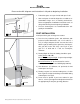
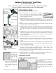

LATCH INSTALLATION
Install Latch after gate and hinges are installed.
1) At the desired height, use the latch plate as a template.
Place it on the side of the gate that will be flush with the
posts. Use a pencil to trace around the inside of the vertical
slot in the latch plate on the gate.
2) Mark a drilling center that is 3/8" above the bottom of the
slot marked on the gate and mid way between the two sides of the slot. (Center of hole
should be 2 1/16" from the edge of the gate). Always drill from the latch plate side of the
gate.
3) Drill a single 3/4" hole through the gate avoiding excessive break out on the other side.
(The entire slot does not have to be drilled out)
4) Install the latch plate on the gate ensuring the bottom of the slot is level with the bottom
of the drilled hole. Install 2 (1.0" x #8) screws in the end of the latch plate into the edge
of the gate. Then install 1 (1.0" x #8) into the countersunk hole on the face of the latch
plate.
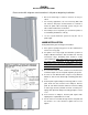
5) Install latch bar so that the thin end is tucked under the loop in the latch plate. (Start
with the bar perpendicular to the plate, tuck the first tooth behind the loop, and drop the
latch bar toward the latch plate until it is resting on it and between the two round protru-
sions on the latch plate.
6) Place the locking bar on the top round protrusion as per the diagram.
7) Place the retainer so that the small rectangular protrusion on the back is facing down
and is installed below the latch bar. Fasten the retainer to the gate using 2(2.0" x # 12)
screws.
8) Install the thumb bar into the back of the handle by pushing the thumb knob through the
handle and rotating it 90 degrees. The two pins on the thumb bar will then sit in the
recesses on the back of the handle.
9) Push the curved end of the thumb bar through the hole in the gate so that it extends
through the slot in the latch plate underneath the latch bar. Install the handle so that
the bar is in center of the hole (use 3 (1.25" x #10) screws)
10) Push the gate to the closed position and mark the gate post at the point where the bot-
tom of the latch bar touches the post.
11) Install the catch plate on the inside face of the gate post using 2 (1.5" x #8) screws, so
that the bottom of the slot is 1/4" below the mark made in #12 above.
Hampton Thumb Latch, Yard Swing
INSTALLATION INSTRUCTIONS
Please review ALL diagrams and instructions in full prior to beginning installation.
Use this instruction in place of those inside of the hardware box.
H:\DESIGN\Installation Instructions\Hampton Latch RevB
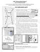
STOP INSTALLATION
Failure to install gate stops will void warranties.
1) Cut stop to be at least as long as the
gate’s edge height.
2) Mount stops to posts (or jambs, if
applicable) using screws and/or weather-
proof wood glue (such as Titebond III).
Position stop with 1/32” gap between
face of gate and stop when gate is
closed.
PADLOCK EYES
INSTALLATION
Optional - If Gate needs to be
locked
1) Install one
padlock eye on
the inside edge
of the latch post/
jamb and the
other on the
gate edge. The
two should align
when door is in closed. Mark hole
locations and pre-drill for screws.
Attach padlock eyes using fas-
teners provided. Padlock not
included.