EVOLUTION Series Controller ® User’s Guide Certified by ICC-ES EPA WaterSense® Certified when used with Smart Connect® For Videos and Information, Visit Toro.
ii
Table of Contents Controller Introduction Timing Mechanism - - - - - - - - - - - - - - - - - - - - - - - - - - - - - - - - - - - - - - - 1 Internal Components - - - - - - - - - - - - - - - - - - - - - - - - - - - - - - - - - - - - - - 2 Installation Cabinet Installation/Template - - - - - - - - - - - - - - - - - - - - - - - - - - - - - - - - - - 3 Power Supply Installation - - - - - - - - - - - - - - - - - - - - - - - - - - - - - - - - - - - - 4 Zone Expansion Module Installation - - - - - - - - - - - - - -
Firmware Update Check Firmware Version of Controller - - - - - - - - - - - - - - - - - - - - - - - - - - - - - - 20 Load New Firmware Version on USB Drive - - - - - - - - - - - - - - - - - - - - - - - - - - - 21 Update Controller Firmware - - - - - - - - - - - - - - - - - - - - - - - - - - - - - - - - - - 21 Factory Reset - - - - - - - - - - - - - - - - - - - - - - - - - - - - - - - - - - - - - - - - - - - 22 Help/Setup Alerts - - - - - - - - - - - - - - - - - - - - - - - - - - - - - - - - - - - - - - - - -
Thank you for purchasing Toro’s new award-winning EVOLUTION® Series irrigation controller, delivering unprecedented control and ease-of-use of your irrigation system! Based on years of customer research, the EVOLUTION® Series irrigation has the perfect balance of simplicity and sophistication. The modern-day programming, unique USB functionality, and smart capability make it an ideal choice for users seeking an advanced irrigation controller without the complexity.
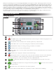
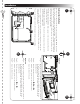
Internal Components Figure 2 1 4 5 7 2 3 6 8 97 1 – Zones and Sensor Terminals VALVE TEST – Use this terminal to test a valve for proper function.
Installation A Cabinet Installation Use this page as a template to mark the screw location of the EVOLUTIONTM cabinet. There are two mounting options for the EVOLUTIONTM. The first option allows you to mount the cabinet with three screws and the second option allows you to mount the cabinet with two screws.
Power Supply Installation WARNING: AC power wiring must be installed and connected by qualified personnel only. All electrical components and installation procedures must comply with all applicable local and national electrical codes. Some codes may require a means of disconnecting from the AC power source installed in the fixed wiring and having a contact separation of at least 0.120" (3mm) in the line and neutral poles. Make sure the power source is OFF prior to connecting the controller.
Zone Expansion Module Installation The EVOLUTION® controller can be expanded using the optional 4-zone (EMOD-4) or 12-zone (EMOD-12) modules to add more zones to the system. Module Installation Figure 9 Figure 10 B B A A Step 1 Step 2 – Open the EVOLUTION® controller door and control panel to access the internal components. – Locate the module slot A and B .
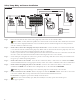
Valve, Pump Relay and Sensor Installation Figure 13 SENSOR SENSOR MV COM 1 PUMP 2 COM Step 1 – Route valve wires from the valves, master valves, pump relay and/or sensor into the controller cabinet. Step 2 – Step 3 – Step 4 – Step 5 – Note: 18 AWG (1.0 mm2) multi-wire sprinkler valve connection cable can be used. This cable is insulated for direct burial and is color-coded to simplify installation.
Setup Screen WELCOME INITIALIZING PLEASE WAIT . . . SETUP SETUP REGION US/CAN LANGUAGE ENGLISH DATE FORMAT MM/DD/YY CLOCK 12 HOUR TIME 12:01AM DATE BEGIN WEEK 01/01/13 SUNDAY Upon power up, the initialization screen will display briefly. On initial power up, the EVOLUTION® will display the SETUP screen. This SETUP screen is only accessed during initial power up or after a factory reset is performed. Once Setup is completed, press the HOME button at any time to return to the main screen.
Basic Schedule Setup Water Day Selection The EVOLUTION® controller allows for flexible watering by giving you four schedule options: 7-day, Even days, Odd days or Interval days. By default, the 7-day schedule is set for the schedule. To set watering days to Odd, Even or Interval, see the Advanced Functions section. Note: At any point, you can return to the previous menu by pressing the Left pressing the HOME button. button or return to the main screen by SCHEDULES button.
Schedule Start Setup By default, the EVOLUTION® controller is set with 1 start time set to OFF. Additional Starts can be added with a maximum of four starts per schedule. Once a start is activated, the schedule will activate the first zone (lowest number). Once it is complete, the second zone will water. The schedule will continue until all zones with runtimes have been activated. Step 1 – Press the Step 2 – Use the Up SCHEDULES button. or Down arrows to navigate to SCHEDULE STARTS. Press SELECT .
Water Now Water Now is used to manually activate a schedule, zone(s), or to test all zones. Note: At any point, you can return to the previous menu by pressing the Left pressing the HOME button. button or return to the main screen by Manually Activate a Schedule Step 1 – Press the WATER NOW button. Step 2 – Use the Up or Down arrows to navigate to SCHEDULE. Press SELECT The selected schedule will run and activate all assigned zones. . Watering will begin.
Adjust Watering ADJUST WATER Adjust Watering is used to increase or decrease the amount of time a zone(s) will water. Step 1 – Press the WATER NOW button. Step 2 – Use the Up or Down Step 3 – Press the Right SCHEDULE A SCHEDULE B ADJUST WATER arrows to select the schedule you want to adjust. arrow to navigate to the next screen. Choose from the two options.
Water Off Turn Off Current Operation Step 1 – Press the WATER OFF button. WATER OFF RESUME WATERING NEXT SCHEDULED START Version 2.0 and later WATER OFF RESUME WATERING NEXT START REMAINS OFF IN 01 DAY IN 02 DAYS Version 2.13 and Newer All currently active automatic schedule(s) and manually activated schedules and zones will turn off. Once the OFF button is pressed, all watering and Auxiliary operation will stop. Step 2 – Press the WATER HOME button.
Advanced Schedules and Functions You can access the EVOLUTION® controller’s advanced functions by pressing the ADVANCED button and then pressing SELECT button to confirm. In the Advanced Functions, you can activate additional schedules, check and set runtimes and start times to all schedules in one screen, set schedule and zone details, assign sensors to the schedules, perform diagnostics test, check firmware version and reset the controller to factory defaults.
Schedule Starts The Schedule Starts function allows you to view the three schedules with all four possible start times. Step 1 – While in the ADVANCED menu, use the Up Press SELECT Step 2 or Down arrows to select the SCHEDULE STARTS. . – Use the Up or Down arrows to navigate to the row that the start time is in. ZONE RUNTIMES A B 04:30A 07:45A 08:00P OFF OFF OFF Step 3 – Use the Left C OFF OFF OFF or Right arrows to navigate to start time you want to edit.
Set Schedule Type Choose Weekday, Odd, Even or Interval watering days. Weekday Scheduling Selecting Weekday scheduling will activate all 7 days of the week. You can disable any of the 7 days as a non-watering day. Step 1 want to edit. Press SELECT Step 2 or Down – While in the ADVANCED/SCHEDULE DETAILS menu, use the Up – Use the Up or Down arrows to select the Schedule you . arrows to navigate to TYPE. Press the Right arrow or SELECT . arrows to select WEEKDAY. Press the Right arrow or SELECT .
Interval Day Scheduling Selecting Interval watering allows you to specify the number of days between watering. For example, selecting an interval of 3 will prompt the controller to water every 3rd day. Select interval from 1–31 days. Step 1 – While in the ADVANCED/SCHEDULE DETAILS menu, use the Up want to edit. Press SELECT or Down arrows to select the Schedule you . Step 2 – Use the Up or Down arrows to navigate to TYPE. Press SELECT Step 3 – Use the Up or Down arrows to select INTERVAL.
Set Monthly Adjust Use the monthly adjust function to allow EVOLUTION® to automatically increase or decrease your watering with respect to the seasons for all zones assigned to the schedule. During the winter and spring months, it may be necessary to decrease watering. In the summer months, it might be necessary to increase watering. Step 1 – While in the ADVANCED/SCHEDULE DETAILS menu, use the Up want to edit. Press SELECT or Down arrows to select the Schedule you .
Set MV/Pump Delay Use the MV/Pump Delay function to set a wait time between activating the master valve or pump, and activating the first zone in the schedule. This delay is usually used to allow the system enough time to build pressure for proper operation, or to fill the irrigation piping system with water. Step 1 – While in the ADVANCED/SCHEDULE DETAILS menu, use the Up want to edit. Press SELECT or Down arrows to select the Schedule you .
Set Active Days Step 1 – Use the Up or Down arrows to select the Auxiliary Schedule you want to edit, then press SELECT Step 2 – Use the Up or Down arrows to navigate to the ACTIVE DAYS, then press the Right . arrow or SELECT . ACTIVE DAYS S Step 3 M T W T – Use the Left F S or Right or turn off arrows to navigate within the days of the week. Use the Up or Down arrows to activate the day for watering. Repeat for all days of the week.
Sensors The Sensors function allows you to assign a rain sensor to each of the schedules. Schedules with a rain sensor assigned will not water when the sensor is activated. Step 1 – While in the ADVANCED menu, use the Up or Down arrows to select the SENSORS. Press SELECT . Step 2 – Use the Up or Down arrows to select the sensor you want to set. Step 3 – Use the Left or Right arrows to select the schedule.
Load New Firmware Version on USB Drive The EVOLUTION® controller’s firmware can easily be updated by downloading the latest software from www.toro.com/evolution/. A USB flash drive is needed for this procedure. Note: Although many USB flash drives may function well with the EVOLUTION® controller, the following USB specifications are recommended: • USB Version 2.0 Compliant • 1–8 GB Memory Size (Smaller memory size will perform faster.
Factory Reset Select this function to reset the controller to the factory default parameters. Schedule B, C and Auxiliary will be disabled and all of their parameters will be cleared or set to OFF. Schedule A will be set with a WEEKDAY schedule with all 7 days active. It will have one start time set to OFF and all zone runtimes set to OFF.
Set Time/Date Step 1 – Press the HELP/SETUP button. Step 2 – Use the Up or Down arrows to navigate to SET TIME/DATE. Press SELECT Step 3 – Use the Up or Down arrows to select TIME or DATE. Navigate to the TIME or DATE parameters using the Right arrow or SELECT HELP/SETUP . . ALERTS CONTACT TORO SET TIME/DATE LOAD FROM USB SAVE TO USB Step 4 – Use the Up or Down arrows to modify the TIME’s Hour and Minutes or the DATE’s Month, Day and Year (Day, Month and Year for International Format).
Preferences Accessing the Preferences Menu Step 1 – Press the Step 2 – Use the Up HELP/SETUP button. or Down arrows to navigate to PREFERENCES. Press SELECT . PREFERENCES LANGUAGE ENGLISH CONTRAST 00 CLOCK 12 HOUR DATE FORMAT MM/DD/YY BEGIN WEEK SUNDAY Set Language You can set the user interface to display in English (default), Spanish, French, German, Italian or Portuguese. Step 1 – While in the PREFERENCES menu, use the Up or Down arrows to navigate to LANGUAGE.
– Use the Up Step 2 or Down arrows to select INCHES or METERS. Press SELECT . Set Volume Unit (Starting Version 2.13) – While in the PREFERENCES menu, use the Up Step 1 Press SELECT – Use the Up Step 2 or Down arrows to navigate to VOLUME UNIT. . or Down arrows to select GPM (Gallons/Minute) or LPM (Liters/Minute). Press SELECT . Home Screen Messages A Title Bar The battery icon indicates that the controller’s VAC power is off and the timer is running under battery power.
Specifications Cabinet Dimensions: • 11.25” W x 7.75” H x 4.5” D (286 x 197 x 114 mm) Internal Transformer, Meets TUV, VDE and SAA Requirements Power Specifications: Output: 24 VAC, 50/60 Hz, 30 VA • US and Canada Internal Transformer, Class 2, UL Listed, CSA Certified (or equivalent) Input: 120 VAC, 60 Hz Output: 24 VAC, 60 Hz, 1.25A • Outside US and Canada Input: 220–240 VAC, 50/60 Hz • Total Maximum Load: 1.0A @ 24 VAC Surge Protection 1.5 KV common mode; 1.
Declaration of Conformity 27
Electronic Compatibility US and Canada: This equipment has been tested and found to comply with the limits for a Class B digital device, pursuant to Subpart J of Part 15 of the FCC Rules. These limits are designed to provide reasonable protection against harmful interference in a residential installation. This equipment generates, uses and can radiate radio frequency energy and, if not installed and used in accordance with the instructions, may cause harmful interference to radio communications.