
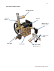
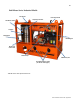
Replacement Part List
11
Oil Fired Gas & Diesel • Rev. 4/7/2016
3. Attach water source to water inlet located on pump. The water source must be attached with a
good quality standard garden type hose (1/2” minimum is required). Connect male fitting into the
female pump inlet fitting. Make sure that the inlet screen/filter is intact and fitted correctly. Turn
on water source. WATER MUST BE IN SUFFICIENT SUPPLY, AND PRESSURE MUST BE
BETWEEN 20 –60 PSI TO ENSURE PROPER AND SAFE OPERATION. Specific attention
should be given if using a well water supply. Ensure water is flowing from end nozzle with the
trigger gun pulled. Deplete system of all air.
4. Start Gas/Diesel Engine
Refer to instructions in engine manual. MAKE SURE THAT THE ENGINE EXHAUST IS NOT
FACING ANY FLAMMABLE MATERIALS.
5. Burner operation
Be sure water is flowing through water heater coil before turning on BURNER switch. Turn
thermostat to desired temperature. Burner will ignite and remain in operation as long as there is
sufficient water flow to satisfy the pressure switch and temperature control.
IF YOU EXPERIENCE IGNITION FAILURE, DO NOT ATTEMPT TO RESTART
BURNER! EXCESS FUEL AND VAPORS MAY HAVE ACCUMULATED AND THE
CHAMBER MAY BE HOT. THE UNIT MUST COOL DOWN BEFORE RESTART CAN
BE ATTEMPTED.
Warning: Condensation on Coil
When cold water is being pumped through the heater coil and the burner is firing, condensation
may form at times on the coil and drip down into the burner compartment. This can be
particularly noticeable on cold, humid days giving the false appearance of a leaking coil. A
leaking coil or system will be evident if the pump keeps cycling with the trigger released. The
pump head pressure should read ‘0’.
Electrically Operated Burners – These models generate 12V from the gasoline engine and
provide the necessary power for the burner. IF YOU REQUIRE UPGRADES OR
MODIFICATIONS TO YOUR EXISTING ELECTRICAL SYSTEM IN ORDER TO
OPERATE YOUR PRESSURE WASHER, THEY MUST BE PERFORMED BY A LICENSED
ELECTRICIAN AND BE COMPLETED IN ACCORDANCE TO ALL APPLICABLE CODES
IN YOUR AREA OF OPERATION. The power supply must be adequate for your specific unit.
Make sure to verify the data plate for your machine’s specific requirements (i.e. voltage,
amperage, etc.).
6. Pressure adjustment - The pressure regulator (unloader) is located on the pump (see pages
19, 21 & 23 diagrams. It controls the pressure being generated by the pressure washer. This
regulator may be adjusted to the desired pressure by turning the adjustment knob. Turning the
adjustment knob clockwise will increase the pressure. NEVER OPERATE SYSTEM AT A
HIGHER PSI THAN THE MAXIMUM RATING. This machine has been adjusted to operate
at a specific maximum pressure as per the machine specifications. Pressure may be reduced for
lighter use by turning the Pressure Regulator/Unloader counter clockwise. If continuing to turn
the unloader clockwise does not increase the pressure, then this implies the maximum has been
reached for