
Data Sheet


Seite 34 von 44
Copyright LZE GmbH 2021
Additional Features
Eine gemeinsame Initiative von
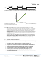
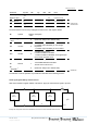
Timing diagram of 3 PWM cycles. t
1
/t and t
2
/t define the duty cycle. The last cycle represents an error state at which no PWM edge
is generated.
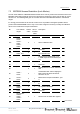
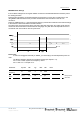
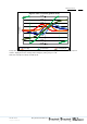
Characteristic curve of the PWM duty cycle vs linearized angle value. The black line represents the maximum possible PWM range.
The green curve shows limited min and max values.
Please note:
Even if a high PWM frequency is used the output update rate is defined by the internal
measurement cycle. Hence several equal output values will be generated. For analog voltage
emulation by using a low pass filter at the PWM output this might still be a preferred setting.
At low PWM frequencies the PWM will only represent the currently valid angle. There is no
averaging of several measurement values even if the internal measurement rate is higher than
the PWM frequency.
The PWM settings can be read by SPI at register 0x000D but only be set at the appropriate
EEPROM address 0x00D.
The 0% and 100% levels of the PWM duty cycle are always at ±180° of the linearized angle.
Hence the zero-point of the PWM can not be chosen arbitrarily. It is only possible to shift the
range around 50% slightly by using the linearization table.
The PWM can only be activated if bit 11 of the lock mode word is set to 1 (refer to 7.3).
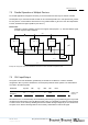
7.4.1 Stand-Alone Operation with PWM Output
It is possible to use the FH3D02 as stand-alone sensor with PWM output. In this case the following steps
are advised:
1. Set a safe lock mode with PWM mode enabled, e.g. 0xDF68 (see chapter 7.3).
2. Set an appropriate measurement configuration by modifying EEPROM address 0x00B (see
5.1.1).
3. Set magnet lost limit (see 7.9) if a different minimum field strength than 1 mT is needed.
4. Calculate and generate an appropriate linearization table and store it in the EEPROM.
5. Configure and enable the PWM by modifying EEPROM address 0x00D (see above).
6. Enable the continuous measurement mode: EEPROM address 0x00E (see 5.1.2).
7. Set a safe application lock mode with PWM enabled, e.g. 0xDFFD (see chapter 7.3).
8. Reboot the device. After the reset cycle the automatic measurement mode will commence and
the PWM output will be activated.
PWM
- CS_N und SCK gem‰fl SPI-Protokoll verwenden
- mit 0x**** dargestellte Daten h‰ngen von Settings ab
- f¸r IDD auf Tabelle verweisen
- Gilt f¸r READY immer aktiv (kein Rdy2hZ, o.‰.)
t = 1/f
PWM
t = 1/f
PWM
t
1
Ö
t = 1/f
PWM
Ö
t
2
-32767 0 32767
LinAngle [LSB]
PWM Duty Cycle
0% 50% 100%