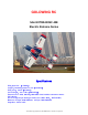
GOLDWING RC 54in EXTRA330SC 40E Electric Extreme Series Specifications Wing Span: 54” (1370mm) Length:Including spinner 52-1/4”(1330mm) Wing Area:614 in²(39.6dm²) Gross Weight:4 to 4.3 lbs(1800-1950g) Electric Power: 4250, 180-220g, 800-1000w class brushless outrunner motors. ESC:40-60A Servos: 4 high torque metal gear mini servos (Hitec HS81、KST315MG) Batteries: 4S Lipo, 2600-3300mah 6S Lipo, 1800-2300mah Propellers: 13X6.5-14X7 All contents copyright 2015, GOLDWING RC Version 2.
Dear Customer, Thank you for purchasing the new GoldWing RC Electric Extreme series aircraft. This manual covers the 55in EXTRA330SC 40E aircraft. Goldwing RC proudly presents 54in EXTRA330SC 40E, Electric Extreme (EX) Series, which is a premium product line of electric RC airplanes designed for unlimited 3D performance. The new 54in EXTRA330SC 40E adopts cutting edge aerodynamic features, such as streamlined canopy, aileron counterbalance, removable side force generators (SFGs).
* By the act of using the final assembled model, the purchaser/operator accepts all resulting liability. GOLDWING RC WARRANTY AND RETURN POLICY GoldWing RC guarantees this product to be free from defects in both material and workmanship at the date of purchase. This does not cover any parts damaged by use, misuse or modification. In no case shall liability exceed the original cost of this kit.
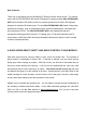
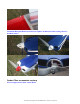
Extra covering provided for small repairs and Covered in Genuine Ultracote / Oracover The air exit for the electric set up still needs to be inside the fuselage behind the rudder tray. Side Force Generators Quick release canopy latch All contents copyright 2015, GOLDWING RC Version 2.
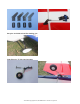
Aluminium Backplate Hollowed-out Electric Spinner included (Excellent cooling effect for brushless motor) Carbon Fiber accessories version: Extra strength Carbon Fiber control Horns All contents copyright 2015, GOLDWING RC Version 2.
One piece air foiled carbon fiber landing gear Light Electric C.F.Tail wheel assembly All contents copyright 2015, GOLDWING RC Version 2.
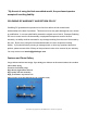
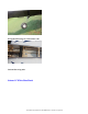
Strengthened fuselage by carbon fiber rods Carbon fiber wing tube. Scheme B White/blue/black All contents copyright 2015, GOLDWING RC Version 2.
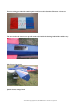
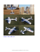
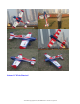
Scheme C Blue /white/ red All contents copyright 2015, GOLDWING RC Version 2.
Scheme D White/blue/red All contents copyright 2015, GOLDWING RC Version 2.
Items Required to Complete This Model 800-1000 Watt, 180-220g class electric motor 40-60A ESC 4 mini size high torque servos (Hitec HS81、KST315MG) Appropriate servo arms (KUZA heavy duty aluminum servo arms recommended, ) Servo wire extensions. two 6”, two 18” Appropriate Lipo batteries (6S 1800-2300mah) All contents copyright 2015, GOLDWING RC Version 2.
Receiver of your choice (minimum 4 channels) RC radio of your choice Shop Supplies/Tools Covering Iron and heat gun Hobby tools such as screwdrivers, hobby knife, drill and drill bits, piers, etc. Thick and Thin CA adhesives 30 minute Epoxy Isopropyl alcohol Ruler or tape measure Blue thread-lock or equivalent Adhesive backed Velcro and Velcro strap for battery retention Note: please read all the instructions before you begin construction.
with unusually large hinge gaps. Aircrafts that utilize a very tight double beveled hinge line and do not normally require this step. Sealing the hinge gaps is therefore left as an option for modellers. Please verify the accessories before assemble: Carbon Fiber control Horns (Bag No. KA07NA2A): 2 horns for ailerons, 1 for elevator, and 1 for rudder. 2” Aluminium Backplate Hollowed-out Electric Spinner (Bag No. KAG0201) Color: Scheme B is white, Scheme C & D is red.
Light Electric C.F.Tail wheel assembly (Bag No. KAG0101) Pushrods kits: Two 1.7x60mm pushrods for ailerons. Two 1.7x90mm pushrods for elevator & rudder. Ball link assembly (Bag No. KAG0011): 8 PCS All contents copyright 2015, GOLDWING RC Version 2.
Servo lead safety clips (Bag No. KAG0019):4 pcs 2” main wheels(Bag No. KAG0145):2pcs New stainless steel Axle kits (Bag No. KA07NH) All contents copyright 2015, GOLDWING RC Version 2.
Extra covering provided for small repairs 3 Hex keys (Bag No. KA07NE) Side force generators (mounted with four M3X18 hand bolts and 2 balsa sheets) All contents copyright 2015, GOLDWING RC Version 2.
3(3x12mm) hex-head bolts & Washers for landing gear Screws for cowl: 4(2.5x12mm) stainless steel tapping screws & 4 PTFE Washers Motor mounting hardware set All contents copyright 2015, GOLDWING RC Version 2.
Construction 1. Rudder Assembly 1.1 Locate rudder, a control horn and base plate. Rudder is driven by push-rod, servo bay is on the right side of the fuselage. 1.2 Locate the slot for control horn on rudder, remove the covering over the slot with heated soldering iron or sharp hobby knife, and make sure you do it on the right side of the aileron. Insert control horn into base plate then into the slot, trace the edge of base plate with hobby knife then remove the underlying covering.
1.3 Use some fine sandpaper to roughen up the root of control horn where will be glued into the slot. 1.4 Fill the slot and coat the root of control horn and the bottom of base plate with 30 minute epoxy, insert the horn into the slot, press it down firmly. Wipe off excessive epoxy with alcohol wipes. Set aside until cured. 1.5 Use CA glue to connect hinges for rudder. 1.6 Cut the covering from the rudder servo slots from corner to corner and iron down inside the openings.
1.7 Use your radio to set the center of servo and then assemble and adjust the length of the control rod. The servo arm should be as close to perpendicular to the control rod as possible while the aileron is at neutral. Double check all screws, bolts and nuts to assure proper installation and operation without binding. Once satisfied, permanently attach the ball links to the servo arms and horns with the supplied screw and nut. 1.
2 Landing Gear Installation 2.1 Locate the landing gear set 2.2 Locate the 2 fiberglass landing gear fairings and the black silicone tubing. Cut through one wall of the tubing along the length. Press the tubing onto the edges of the fairing as shown and secure glue. All contents copyright 2015, GOLDWING RC Version 2.
2.3 Bolt the main gear to the bottom of the fuselage using the supplied bolts Adjust the position of the landing gear fairings, the secure with glue (shoe goo type). All contents copyright 2015, GOLDWING RC Version 2.
2.4 Install the wheel axles to the landing gear and tighten the nylon-insert lock nut. Install one wheel collar onto the axle. Use a second wheel collar as a guide to leave a gap on the inboard of the axle. Use a small drop of thread-lock and tighten in place. Slide the wheel onto the axle and install a second wheel collar also using thread-lock on the set screw. All contents copyright 2015, GOLDWING RC Version 2.
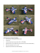
2.5 Fit the wheel pant in place and install using the 2mm hex-head bolts & Washers. Use thread-lock to secure the screws in place. Repeat the above steps for the other main gear. 2.6 Tail wheel assembly for electric airplanes. 2.7 Tail wheel kit is pre-assembled in factory, for safety, please remove all screws and then reassemble with thread locker. All contents copyright 2015, GOLDWING RC Version 2.
2.8 Drill 2 mm holes on the bottom rear of the fuselage, secure the tailwheel bracket with the provided screws. For best results, the pivot point of the assembly should be over the hinge line of the rudder. 2.9 Drill a hole on the bottom of rudder, 70-100mm away for the hinge line. Secure the tail wheel spring with provided self-threading screw. All contents copyright 2015, GOLDWING RC Version 2.
3. Wing Assembly 3.1 Locate two wing panels with ailerons, and two set of control horns and base plates. 3.2 Locate the slot for control horn on aileron, remove the covering over the slot with heated soldering iron or sharp hobby knife, and make sure you do it on the bottom side of the aileron. Insert control horn into base plate then into the slot, trace the edge of base plate with hobby knife then remove the underlying covering. 3.
3.5 The slots for CA hinges are pre-cut. Insert CA hinges half way into the hinge slots on aileron, apply a drop of thin CA to secure the hinges. Then insert all hinges into slots on the wing at once, align aileron with the wing, move the aileron up and down a few times to reach the minimal hinge gap while still allowing full deflection of the aileron. When satisfied, apply more think CA on both top and bottom sides of each hinges. 3.
3.7 Use your radio to set the centers of each servo and then assemble and adjust the length of each control rod, KUZA 1” aluminium CNC servo arm is recommended for aileron control (sold separately). The servo arm should be as close to perpendicular to the control rod as possible while the aileron is at neutral. Double check all screws, bolts and nuts to assure proper installation and operation without binding.
3.9 Repeat this process for the other wing half. 4 Elevators Assembly 4.1 Find the control horn slots on bottom side the elevators, use the method described in 1.21.4 to install control horns for elevators. 4.2 Elevator horn slot is located on the left side of elevator. Remove covering over the hole for horizontal stabilizer on fuselage. Removing covering on the central part of horizontal stabilizer is recommended for better glue bonding.
4.3 Glue the nylon hinges for the elevator with epoxy glue. 4.4 Glue the hinges for the elevator with CA glue. All contents copyright 2015, GOLDWING RC Version 2.
4.5 After installing the elevator, use supplied balsa pieces to fill gap behind the elevator as shown below 4.6 Locate the slots for elevator servo, remove covering. Connect wire extension to your servos before feeding the wire into fuselage. Install servo with screws supplied by servo manufacturer. 4.7 Use your radio to set the servo center position and install the large control horn onto the servo.
geometry. When satisfied, screw the ball link to the servo arm and control horn. KUZA 1” aluminium CNC servo arm is recommended for elevator control, the servo arm should be as close to perpendicular to the control rod as possible while the elevator is at neutral. Double check all screws, bolts and nuts to assure proper installation and operation without binding. 5 Motor Mounting 5.1 Blind nuts are pre-installed behind the firewall. 5.
6 Cowl Installation 6.1 Test fit the cowl first, make sure it fits well with canopy and fuselage. 6.2 Drill 2mm holes on cowl and fuselage. 6.3 Enlarge the holes on cowl with 2.5mm drill bit. All contents copyright 2015, GOLDWING RC Version 2.
6.4 Secure the cowl with 2.5X12mm self-threading screws .& PTFE Washers. You may install spinners and properlers afterward. 7 Final Radio System Installlation 7.1 Whether you 72 MHz systems or the newer 2.4 GHz systems, proper radio installation and care is vital to the safe and reliable operation of your aircraft. Follow the manufacturer’s instruction for installation guidance of receivers and batteries paying attention to factors such as vibration isolation, adequate cooling, and clearances. 7.
7.3 Your receiver battery(s) can be mounted in a variety of locations depending on your balance needs. Regardless of where you mount your batteries it is vital that they are very secure with no possibility of coming loose. Use double sided velcro to hold the batteries from sliding around and then use zip ties or velcro straps to secure them tightly in place. 7.4 Servo and battery leads are the life blood of your aircraft.
9. Final Assembly and Pre-Flight Inspections 9.1 Before arriving at your flying field, be sure all your batteries are properly charged and all radio systems are in proper working order. 9.2 Install the wings onto the fuselage being careful to align the wing tube with the wings and not force it. The wing tube may be initially tight but will loosen some with use. Guide your servo wires into the fuselage openings and connect to the proper aileron channels. Servo clips are recommended.
9.5 Check all control surfaces for secure hinges by performed a slight tug on the control surfaces and observing if there is any give in the hinges. Check all control rods, ball links, servo screws, etc. for proper operation and installation. 9.6 Check your batteries and perform a proper range check once again with the engine off and running. Be sure all surfaces are moving in the correct direction and the proper amount for your flying setup.
JR 26mm/1in No. KAG0S76J KUZA Heavy duty Alloy Servo Arms FUTABA 26mm/1in No. KAG0S70F HITEC 26mm/1in No. KAG0S70H All contents copyright 2015, GOLDWING RC Version 2.
JR 26mm/1in No. KAG0S70J www.goldwingrc.com All contents copyright 2015, GOLDWING RC Version 2.