
Installation Guide


Areas of Application
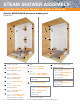
Interior showers with or without curbless applications.
Interior intermittent use steam showers (e.g., residential applications). See details
K-SSH-K or K-SSH-KB in the Schluter
®
-Shower System Installation Handbook for
more information.
Over wood or concrete subfloors.
Limitations
Certain glass tiles may not be compatible with bonded waterproof membranes and/
or may require special setting materials. Consult glass tile manufacturer and
Schluter
®
-Systems for more information.
Certain moisture sensitive stones, e.g., green marble, or resin-backed tiles may not
be appropriate for use in wet areas such as showers or may require special setting
materials. Consult stone supplier and Schluter
®
-Systems for more information.
Do not use sawn lumber curbs on concrete subfloors subject to moisture migration.
Requirements
Plywood, OSB, or concrete subfloor must be clean, even, and load bearing.
For wood substrates, subfloor/underlayment configuration according to detail
DH-W16-T, DH-W19-T, DH-W24-T, or DH-W-S.
For curbless applications: Recessing the floor of a bathroom must be done in a way
that preserves the structural integrity and safety of the construction. This may require
the services of a qualified design professional (e.g., architect, engineer, etc.).
Solid backing – gypsum wallboard, cementitious backer unit, fiber-cement
underlayment, fiber-reinforced water-resistant gypsum backerboard/underlayment,
coated glass mat water-resistant gypsum backerboard, Portland cement mortar bed,
concrete, or masonry.
Minimum KERDI-BOARD thickness – 1/2" (12.5 mm) for studs spaced at
16" (40.6 cm) o.c. and 3/4" (19 mm) for studs spaced at 24" (61.0 cm) o.c.
KERDI-BOARD shall be fastened to wood or metal framing with appropriate screws
(i.e., coarse thread wood screw for wood studs and self-tapping for metal studs) and
corresponding KERDI-BOARD-ZT washers. Screws must reach a depth of at least
3/4" (20 mm) in wood studs and 3/8" (10 mm) in metal studs. Maximum allowable
on-center fastener spacing is 12" (30 cm) for walls and 6" (15 cm) for ceilings.
KERDI or KERDI-BOARD shall be installed up to the height of the showerhead at
minimum.
Any protrusions through the KERDI or KERDI-BOARD (e.g., showerhead, mixing
valve, etc.) must be treated with KERDI-SEAL-PS/-MV seals, KERDI-FIX or suitable
sealant.
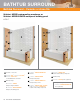
Base – KERDI-SHOWER-ST/-L/-LS or Portland cement mortar bed.
Ramp – KERDI-SHOWER-SR or Portland cement mortar bed.
Curb – KERDI-SHOWER-SC, KERDI-BOARD-SC, KERDI-BOARD, concrete,
masonry block, or sawn lumber sheathed with solid backing (see above).
Bench – KERDI-BOARD-SB, KERDI-SHOWER-SB, KERDI-BOARD, concrete,
masonry block, or sawn lumber sheathed with solid backing (see above).
KERDI-DRAIN/-LINE shall be properly supported.
KERDI-DRAIN/-LINE shall be connected to the waste line; use ABS cement for ABS
drains, PVC cement for PVC drains, a no-hub coupling for stainless steel drains with
no-hub outlets, and thread sealing compound or tape for stainless steel drains with
threaded outlets.
When using the stainless steel KERDI-DRAIN bonding flange, use KERDI-FIX to bond
KERDI to the drain.
DITRA-HEAT heating cables must be installed in the DITRA-HEAT or DITRA-HEAT-
DUO membrane. KERDI must be installed over the heating cables and DITRA-HEAT/-
DUO in the shower.
Due to the installation of the DITRA-HEAT membrane on top of the shower tray, it is
necessary to raise the height of the KERDI-DRAIN/LINE. Installation of DITRA-HEAT
membrane on the substrate under the detachable center section for KERDI-DRAIN or
under the KERDI-LINE channel body support will provide the proper height
adjustment.
When a curb is used, the heating cables must be installed over the curb in a
3/4" wide x 1/4" deep routed section and encased in thin-set mortar. DO NOT install
the heating cable under the curb or go through the curb, as this could cause
damage to the heating cable and curb. After the heating cable is installed,
apply KERDI over the routed section of the KERDI-BOARD-SC curb.
A dedicated heating cable is recommended in the shower area to allow for simple
disconnection without an impact on the bathroom floor heating in the event that the
shower heating cable is damaged. Multiple heating cables may be installed on a single
thermostat, up to the 15 amp limit.
Heating cables must be installed 3 studs from the edge of the KERDI-LINE flange and
2 studs from the edge of the KERDI-DRAIN flange.
Safety
Repairs to the DITRA-HEAT heating cable in the shower may not be approved. Verify
with the local inspector or authority having jurisdiction (AHJ). Flood testing the shower
is recommended before re-tiling.
Heating cable factory splice (i.e., cold lead splice) must not be installed in the shower
area.
Substrate Preparation
Verify that subfloor panels and solid backing are properly fastened to framing members.
Any leveling of the subfloor must be done prior to installing KERDI-SHOWER-ST/-
L/-LS/-SC/-SB/-SR, KERDI-BOARD-SC/-SB, DITRA-HEAT, and DITRA-HEAT-DUO
membranes.
Solid Backing Materials
Gypsum wallboard – ASTM C1396/C1396M
Cementitious backer unit – ANSI A118.9 or ASTM C1325
Fiber-cement underlayment – ASTM C1288
Fiber-reinforced water-resistant gypsum
backerboard/underlayment – ASTM C1278
Coated glass mat water-resistant gypsum backerboard – ASTM C1178
Portland cement mortar – ANSI A108.1B
Concrete
Masonry
Setting and Grouting Materials
Unmodified thin-set mortar – ANSI A118.1
Grout – ANSI A118.3, A118.6, A118.7
Installation Specifications
Solid backing panels – follow manufacturer’s instructions
Portland cement mortar bed – ANSI A108.1B
Tile – ANSI A108.5
Grout – ANSI A108.6, A108.10
Other Considerations
Acceptance of electric floor warming in a shower and this detail must be verified by
the local inspector or authority having jurisdiction (AHJ).
KERDI is required on top of DITRA-HEAT installations in the shower. Schluter
®
-
Systems chooses to be conservative and to ensure everything is protected. Note:
DITRA-HEAT-E-HK heating cables are rated for wet applications per CAN/CSA-
C22.2 No.130-03.DITRA-HEAT membranes have been found to meet or exceed
the requirements of ANSI A118.10.
Curbless tiled showers rely on the slope of the floor to effectively contain water in the
immediate shower area and direct water to the drain. Given the wide range of
potential configurations, it isn’t possible to address them all in this Handbook.
For curbless applications: waterproofing must be installed in all areas subject to water
exposure.
Schluter
®
-SHOWERPROFILE-WS/-WSK system profiles can be used to form a
splashguard at the entrance of curbless showers.
Various building codes and other sources, such as the Americans with Disabilities Act,
include specific requirements for disabled access in public buildings and must be
consulted when applicable. Areas of interest may include degree of slope, clearance,
and supporting structures such as grab bars.
Shower grab bars must be anchored in the structure or solid blocking behind KERDI-
BOARD.
When KERDI-SHOWER-ST/-L/-LS tray dimensions do not match the dimensions of
the shower compartment, the tray may be cut or extended with dry pack mortar.
When KERDI or KERDI-BOARD and tile are installed on the ceiling, the solid backing
and fasteners must be able to support the load of the tile and setting and grouting
materials.
A water test is recommended before setting tile to verify a successful installation. Wait
24 hours minimum after the membrane installation is complete to allow for final set of
thin-set mortar and ensure waterproof performance at seams and connections. For
curbless showers a temporary dam (e.g., a 2x4 and silicone sealant, plastic sheeting
and sand, etc.) must be provided at the threshold to perform the water test.
Schluter
®
-Systems profiles may be used to finish and protect outside corners and
eliminate the use of sealant at inside corners.
Schluter
®
-SHOWERPROFILE-S/-R profiles eliminate the need for cutting wedges of
tile by covering the exposed wall area where the floor slopes to KERDI-LINE.
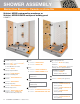
Showers – Ceramic or stone tile
DH-SH-17
Schluter
®
-DITRA-HEAT Shower Application
SHOWER ASSEMBLY — Schluter
®
-DITRA-HEAT 11
Note: Please refer to the Schluter
®
-DITRA-HEAT Installation
Handbook for installation instructions and warranty criteria
for the Schluter
®
-DITRA-HEAT floor warming system.