LCD12864-COG LCD Module User Manual Rev.
LCD12864-COG Table of Content 1. Bsaic Specifications……………….………………………………………………3 Display Specifications………………………..……………………………………………………………….3 1.2 Mechanical Specifications………………..…………………………………………………………………..3 1.3 Circuit Diagram…..………………………..…………………………………………………………………..3 1.4 Terminal Function…..…………………..……………………………………………………………………..4 1.1 2. Absolute Maximum Ratings...…….………………………………………………5 3. Electrical Characteristics………….………………………………………………5 3.1 3.2 3.3 3.4 DC Characteristics……..………………..
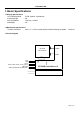
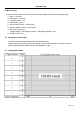
LCD12864-COG 1. Bsaic Specifications 1.1 Display Specifications 1>LCD Display Mode 2>Viewing Angle 3>Driving Method 4>Backlight : FSTN, Positive, Transflective : 6H : 1/64 Duty, 1/9 Bias : NC 1.2 Mechanical Specifications 1>Outline Dimension : 39.5 x 31.1 x 2.0mm (See attached Outline Drawing for Details PAGE14) 1.
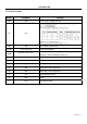
LCD12864-COG 1.4 Terminal Function Pin No. Pin Name Function 28 VDD 27 P/S 26 C86 21~25 V0,V1,V2,V3,V4 16-20 C2-,C2+,C1+,C1-,C3+ 15 VOUT 14 VSS 6-13 D0-D7 5 /RD Read (/RD ) control signal input. 4 /WR Write (/WR ) control signal input. 3 A0 2 /RES Reset 1 /CS1 chip selection input Power supply voltage (Positive) MPU interface selection pin LCD driving voltages. When internal DC-DC voltage converter is used, external capacitor is connected between these pins.
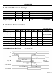
LCD12864-COG 2. Absolute Maximum Ratings Items Symbol MIN. MAX. Unit Condition Supply Voltage VDD -0.3 +3.3 V VSS = 0V Input Voltage VIN -0.3 VDD+0.3 V VSS = 0V Operating Temperature TOP -10 +60 ℃ No Condensation Storage Temperature Tst -20 +70 ℃ No Condensation 3. Electrical Characteristics 3.1 DC Characteristics Vss = 0V,Top = 25℃ Items Symbol MIN. TYP. MAX. Unit Operating Voltage VDD 2.8 3.0 3.3 V VDD Input High Voltage VIH 0.
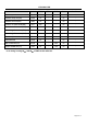
LCD12864-COG Items Symbol MIN. TYP. MAX.
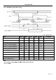
LCD12864-COG 3.3.2 6800 Mode System Bus Timing Vss = 0V,Top = 25℃ Items Symbol MIN. TYP. MAX.
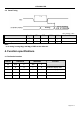
LCD12864-COG 3.4 Reset Timing Vss = 0V,Top = 25℃ Items Reset time Reset Low pules width Symbol MIN. TYP. MAX. Unit Condition Tr - - 2.5 µS - Trw 2.5 - - µS - Note: *a. all timing is using 20﹪ and 80﹪ of VDD as the reference. 4. Function specifications 4.
LCD12864-COG 4.2 Basic Setting To drive the LCD module correctly and provide normally display, please use the following seting 1> ADC = 0 (normal) 2> SHL select = 1(reverse) 3> LCD Bias Select = 1/9 4> Initial Display Line = 0 5> Entire Display ON/OF = OFF(normal) 6> Reverse Display ON/OF = OFF(normal) 7> Set Power Control Set: Voltage follower = ON,voltage converter = ON,Voltage regulator = ON 8> Display ON/OF =ON 4.3 Resetting the LCD module The LCD module should be initialized bu using /RES terminal.
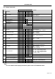
LCD12864-COG 4.5 Display Commands Code D6 D5 D4 D3 D2 D1 Display ON/OFF 0 1 0 1 0 1 0 1 1 1 2 Display start line set 0 1 0 0 1 Display start address Set the display RAM display start line address 3 Set Page Address 0 1 0 1 0 1 1 Page address Set the display RAM Page address 0 1 0 0 0 0 1 Col. Add Set the upper-4-bit of column address counter 4 Ser Column Address (Upper-4 bits) Ser Column Address (Lower-4 bits) 0 1 0 0 0 0 0 Col.
LCD12864-COG 4.6 Basic Operating Sequence 4.6.
LCD12864-COG 5. Inspection Standards Item Criterion for defects (1) Non display (2) Vertical line is deficient (3) Horizontal line is deficient (4) Cross line is deficient Size Φ(mm) Acceptable number Φ≤0.3 Ignore (note) 0.3<Φ≤0.45 3 0.45<Φ≤0.6 1 0.6<Φ 0 Length (mm) Width (mm) Acceptable number L≤10 W≤0.03 Ignore 5.0≤L≤10 0.03
LCD12864-COG 6. Handling Precautions 6.1 Mounting method A panel of LCD module made by our company consists of two thin glass plates with polarizers that easily get damaged. And since the module in so constructed as to be fixed by utilizing fitting holes in the printed circuit board (PCB), extreme care should be used when handling the LCD modules. 6.2 Cautions of LCD handling and cleaning When cleaning the display surface, use soft cloth with solvent (recommended below) and wipe lightly.
LCD12864-COG Page 14 of 14