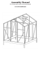
E X10 Assembly Manual for Polycarbonate Greenhouses 6 x 6 Greenhouse
Assembly Manual for Polycarbonate Greenhouses 6 x 6 Greenhouse Table of Contents Introduction · · · · · · · · · · · · · · · · · · · · · · · · · · · · · · · · · · · · · · · General Advice · · · · · · · · · · · · · · · · · · · · · · · · · · · · · · · · · · · · About This Manual · · · · · · · · · · · · · · · · · · · · · · · · · · · · · · · · · Maintenance · · · · · · · · · · · · · · · · · · · · · · · · · · · · · · · · · · · · · · Parts List · · · · · · · · · · · · · · · · · · · · · · · · · · · · · · · · · ·
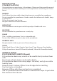
01 INTRODUCTION CONGRATULATIONS Congratulations on purchasing a Greenhouse. Please read the assembly manual and familiarise yourself with the parts and steps before assembling your Greenhouse. NOTICE It will take at least two adults about three hours to assemble the greenhouse. Do not assemble the greenhouse if tired or under the influence of alcohol, drugs or medication. Follow the manual step by step. Keep this manual for future reference. IMPORTANT The Greenhouse contains parts with sharp edges.
02 BASE As per your choice, you may receive a greenhouse with or without a pre-fabricated base kit. Either way, this greenhouse must be secured to a firm base. The Base must be level and square. Before assembling the greenhouse, you must prepare a proper foundation. Two foundation options are provided in this manual. The concrete foundation option is recommended for a stronger installation. SITE SELECTION The greenhouse should be placed in an area that receives direct sunlight and gets shielded from wind.
03 SEALING Sealing the greenhouse by applying glue or tapes between the polycabonate sheets and aluminum profiles will keep insects out and provide better stability against wind. Sealant and glue gun are not included. PARTS Identify all parts using the parts list on next page and labels on the parts. Layout each part needed for a step before working on that step. MAINTENANCE Inspect the greenhouse periodically. When the greenhouse needs cleaning, use a gentle detergent.
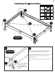
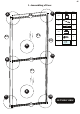
O INGS L MANUA ctis. MERS ctis. S SIZES 05 Assembling of Pre-fabricated Base LO EK m WE ® EKO m RE8 ZES 10X ® L O AEK E W m ® EKO s.com S GS SIZE AL 0 MANU ro OP E OUR Aw.com NINGS 0 13X10 KO® roWE U-S O® s ® Part No. A 3 2 A 1 Part Qty. 1 2 2 2 3 4 F3 16 A B 3 3 2 1 A OUTSIDE VIEW 3 A B Take the fully assembled base to the chosen site and secure the base to the ground.
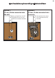
06 Two foundation options with pre-fabricated Base Option 1 Corner Stakes mounted into the soil Easy and quick to install. Suitable to use in areas with less extreme weather Option 2 Corner Stakes mounted into concrete Best option if you want your greenhouse fully secured.
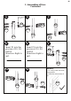
07 1. Assembling of Door A F D2 P1 D1 D4 Part No. Part Qty.
08 1. Assembling of Door Continued A C B D2 D1 D3 F1 F1 D3 D1 D1 F1 D E F Insert P1 into the grooves of D1, D2, and D3. Direction: Right to Left. Insert P1 into the grooves of D1, D3, and D3. Direction: Right to Left. D2 F1 D4 Notice: H G D3 D4 F1 1. D1 and D4 are not interchangeable. 2.
09 2. Assembling of Roof Vent Part No. Part W1 1 W2 2 W3 1 W4 1 S8 1 S9 1 F2 4 F8 1 F9 1 P2 1 B W1 Qty. A W2 W2 C P2 E D W3 INSIDE VIEW A B C W2 F2 W1 D E Insert P2 into the grooves of D1, D3, and D3.
10 2.
11 3. Assembling of Main Frame Part No. Part Qty.
12 3. Assembling of Main Frame Continued A B F4 F4 4 C D F4 6 F4 5 8 F4 E F4 17 F4 Notice 1. Do not tighten the nut. Only loosely screw it onto the thread. 2. Note that the orientation of the bolt and the nut cannot be changed. See the diagram below for better undertanding.
13 3. Assembling of Main Frame Continued 7 7 7 7 4 5 A A B 4 6 Part No. Part Qty. OUTSIDE VIEW Front(Door) 4 2 5 1 6 1 7 4 10L 1 10R 1 4 F4 16 Repeat two times A 7 B 7 INSIDE VIEW 5 4 5 Notice: 1. Nuts face inside. 2. Fasten these two nuts.
14 3. Assembling of Main Frame Continued B 7 OUTSIDE VIEW 4 6 Notice: 1. Nuts face inside. 2. Fasten these two nuts.
15 3. Assembling of Main Frame Continued C D 10L 5 10R 5 E F4*3 F F4 Repeat four times 7 G Notice F4 1. Fasten the nuts each time after 7, 10L, or 10R is connected to frames 4, 5 or 6. 2. About step E, F, and G, only insert bolt F4 into the grooves. Do not screw the nut. 10R b b a a Side Top View a a b Door 10L b 3. About step E, note that each 7 has two grooves where F4 bolts will be inserted into.
16 4. Assembling of Backwall 12 15 Part No. Part 12 A B Qty.
17 4. Assembling of Backwall Continued A C B F4*2 F4*2 12 Insert P3 into grooves of 7, 10L till P3 rests on 5. 15 Repeat two times F D E Insert P5 into grooves of 10L, 10R till P5 rests on 5. Insert P3 into grooves of 10R, 7 till P3 rests on 5. 12 P3 H G I 15 12 P5 P3 J Insert P6 into grooves of 10L, 10R till P6 goes into the top groove of 15. K Insert P4L into grooves of 10R, 7 till P4L goes into the top groove of 12.
18 4. Assembling of Backwall Continued Part No. Part Qty.
19 4. Assembling of Backwall Continued A B 14 10L 14 12 15 12 7 C D 10L 14 14 15 12 12 7 Notice 1 1. About Step A or D, two Bolt F4 will be used. One comes from 7 and the other from 12. Both of these two bolts were inserted into respective grooves in previous steps. You do not need new bolts here, only the nuts. 2. Fasten the nuts. Notice 2 1. About Step B or C, three Bolt F4 will be used. One from 12, one comes from 10L/10R, and the rest from 15.
20 5. Assembling of Front wall Part No. Part Qty.
21 5. Assembling of Front wall Continued Part No. Part Qty. 13 1 F4 2 C 13 C 9 9 6 5 OUTSIDE VIEW Back C Repeat two times 13 Notice 1. About Step B, only insert Bolt F4 into the groove. Do not screw the nut. 2. About Step C, one Bolt F4 will be used. It comes from 9 and was inserted into 9 in Step B. You do not need new bolts here, only the nuts. INSIDE VIEW 9 Fasten the nut 3. Note the orientation of 13. 4. Notice that in step A and B, 9 has one of its end removed.
22 5. Assembling of Front wall Continued 12 Part No. Part 12 A A Qty.
23 5. Assembling of Front wall Continued B A F4*2 Insert P3 into grooves of 7 and 9 till P3 rests on 6. Repeat two times 12 Only insert the bolts. Do not screw the nuts. Repeat two times D C 12 Insert P4R into grooves of 7 and 9, till P4R goes into the top groove of 12. P3 Repeat two times E F Insert P4L into grooves of 7 and 9, till P4L goes into the top groove of 12. Insert P7 into the top groove of 13. Have a person or a chair to buttress the front wall.
24 5. Assembling of Front wall Continued Part No. Part Qty. B3 4 F4 4 A B B A 6 5 OUTSIDE VIEW Back B A Attach B3 to 7 and 12 using pre-inserted Bolts F4. Fasten the Nuts F4. Repeat two times. Attach B3 to 9 and 12 using pre-inserted Bolts F4. Fasten the Nuts F4. Repeat two times.
25 6. Assembling of Roof Frames Part No. Part Qty.
26 6. Assembling of Roof Frames Continued A B Only insert the bolts. Do not screw the nuts. F4 Only insert the bolts. Do not screw the nuts. F4 10R 10L C 8 8 Repeat four times 7 INSIDE VIEW 7 OUTSIDE VIEW PROFILE VIEW Notice 1. About Step C, note that the profile view of 7 and 8 (the diagram on the right) shows the exact placement of 8. Note that the groove of 8 faces upward. 2. About Step C, the F4 Screw goes into the groove of 7 that faces either side wall of the greenhouse, groove a.
27 6. Assembling of Roof Frames Continued A Part No. Part Qty.
28 6. Assembling of Roof Frames Continued A-1 16 8 A-2 F4a 16 8 Fasten the nut INSIDE VIEW 7 A-3 16 8 7 OUTSIDE PROFILE VIEW groove a b 16 e v o o r g INSIDE VIEW 7 INSIDE VIEW Notice: 1. Repeat Step A four times. 2. Notice that 16, like 7, has two grooves for bolts. The groove of 16 where the bolt of 8 goes into is the upper groove, groove a. 3. Note that Bolt and Nut set F4a in Step A-1 was one of the bolts pre-inserted into the holes of 8 in previous steps. 4.
29 Part No. Part F4 6. Assembling of Roof Frames Qty. Continued 9 16 A 16 B 16 16 OUTSIDE VIEW Front 16 16 Notice Note that 16 has two grooves, groove a on the upper side, and groove b on the lower side.
30 6. Assembling of Roof Frames Continued A F4 16 F4 16 B 16 F4 16 Notice 1. Note that the numbers of F4 bolts inserted into grooves of 16 in Step A and Step B are different. 2. Only insert the bolt. Do not screw the nut.
31 7. Securing of Frames Part No. Part Qty.
32 A-1 7. Securing of Frames Continued A-2 17 16 16 17 16 16 OUTSIDE Profile View OUTSIDE Profile View B A-1 A-2 Slide 17 into 16. The pre-inserted bolt F4 on 17 goes into the upper groove of each 16. 16 Repeat two times, till the four Bolt F4 on both ends of 17 go into the four upper grooves of 16. Fasten the Nuts. 13 F6 B B4 F4b 16 Notice 9 Outside View Front About Step B, note that three Bolt F4 will be used.
Part No. Part 33 Qty. B4 2 F4 8 B6 2 B5 4 F4 24 18 1 Roof Vent 1 7. Securing of Frames Continued A C B D A B A E F A OUTSIDE VIEW Front A B5 16 16 F4*4 Inside View Notice 1. Four Bolt F4 will be used in step A. They are inserted into the lower groove of 16 in this very step. 2. Note how B5 and the bolts are connected. 3. Fasten the nuts 4. Repeat four times. 8 is rendered invisible in this diagram for better visibility..
34 7. Securing of Frames Continued B 16 B6 Notice 1. Four Bolt F4 will be used in step B. They are inserted into the lower groove of 16 in this very step. 2. Note how B6 and the bolts are connected. 3. Fasten the nuts 4. Repeat two times. 16 17 is rendered invisible in this diagram for better visibility.. F4*4 Inside View C D 16 16 F4a F4b 10L F4a B4 B4 F4c F4c F4d F4d Notice 1. In step C and D, each step utilizes 4 Bolt F4.
35 7. Securing of Frames Continued E-2 Notice Step E-1 Slide 18 into the position shown in E-1. The head of Bolt F6 should go into the groove of 18. Fasten the Nuts of both F6. Step E-2 Slide the door into the position shown in E-2. The casters on the back of the door should rest on the bulging part of 18. 18 Caster DOOR 9 Outside Profile View F 17 16 16 Roof Vent Outside View Front Notice About Step F, slide the roof vent into the left track of 17.
36 8. Assembling of Middle Frame Part No. Part Qty.
37 A-1 8. Assembling of Middle Frame Continued A-2 Slide 19 to the position shown on previous page. The head of the Bolt F4 on 8 and 4 should go into the groove of 19. 19 Before the head of the Bolt F4 on 4 goes into the groove of 19, Insert a Bolt F4 into the groove of 19 from the lower end. Fasten the Bolt F4 on 8 and 4 with nuts. Now there should be a Bolt F4 free to move inside the groove of 19. INSIDE VIEW B-1 B-2 Slide 20 to the position shown on previous page.
38 9. Assembling of Roof Vent Holder B A Part No. A 12 Part Qty.
39 9.
40 9. Assembling of Roof Vent Holder Continued A B F4 B7 B3 12 F4 Screw on the nut of Bolt F4 but do not fasten it. F4 12 Screw on the nuts of Bolt F4 but do not fasten them. Note that at this step, the orientation of B7 does not matter. C-1 C-2 Place the newly assembled 12 next to the roof vent. Note that the three pointers of B7 must face toward the ridge. Fasten the four F4 Bolts on two B3 with nuts. 12 Locate two previously inserted F4 Bolts, one in the groove of 20.
41 9. Assembling of Roof Vent Holder Continued Roof Vent Note that B7’s position decides the opening height of the roof vent. Fasten the nuts on B7 when you are satisfied with the opening. W4 20 B7 D-2 D-1 23 F4 23 9/10 Step D-1 and D-2 F4 Inside View This step utilizes two previously inserted F4 Bolts, one in the groove of 9 (or 10L/10R for the backwall), the other in the groove of 7. Slide these two bolts to the position shown on the diagrams above and place 23 under the bolts. Fasten the nuts.
42 10.
43 10. Assembling of Side Braces Continued Step E-1 and E-2 This step utilizes two previously inserted F4 Bolts, one in the groove of 19 the other in the groove of 7. Slide these two bolts to the position shown on the diagrams on previous page and place 22 under the bolts. Fasten the nuts.
44 11. Assembling of Panels P8 A P8 P8 Insert Panel P8. B P8 Insert Panel P9. P8 P8 C Insert Panel P10. P10 P9 P9 Part No. Part Qty.
45 Polycarbonate Panel Layout Back Left OUTSIDE VIEW Front
46 12. Assembling of Gutters and Caps Part No. Part Qty.
47 12. Assembling of Gutters and Caps Continued A A 25 8 16 7 25 OUTSIDE VIEW FRONT B C Slide 25 into the groove of 8 OUTSIDE VIEW FRONT PROFILE D 17 16 16 S6R S6L S8 E 18 Door S7 Step BCDE are about adding plastic caps. Cap used in Step B is S6R. Cap used in Step C is S6L. Cap used in Step D is S8. Cap used in Step E is S7. Apply a small amount of silicone to secure these caps.
48 Securing the greenhouse to the prefabricated Base OUTSIDE VIEW Front Part No. B2 Part Qty.
49 Securing the greenhouse to the prefabricated Base Continued A 4 A 5 A A A A 4 A 6 A TOP TO BOTTOM VIEW A Get inside the greenhouse and locate all the F4 Bolts on 4, 5, and 6. Unscrew the nuts. Attach B2 to the bolt, fasten the nut to secure the greenhouse to the base. There are 16 F4 Bolts.