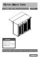
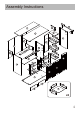
WF531421 Width-45.3inch Depth-17.7inch+11.
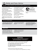
! Safety and Care Advice Important – Please read these instructions fully before starting assembly • Check you have all the components and tools listed on the following pages. • During assembly do not stand or put weight on the product, this could cause damage. • Remove all fittings from the plastic bags and separate them into their groups. • Assemble the item as close to its final position (in the same room) as possible.
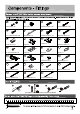
Cam Bolt x 42 Cam lock x 42 8*30mm Dowel x 64 4*35mm Screw x 30 3.
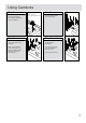
Using Camlocks Step 1 Connect the male camlock as diected in the assembly instructions using a scewdriver. 1 Step 2 DO NOT OVER TIGHTEN. NE PAS SERRER EXCESSIVEMENT. 2 Push the male camlock into the entry hole. 4 Step 3 Insert the female camlock as shown in the instruction. Note:ensure that the arrow on the top of the camlock points towards the entry hole for the male camlock. 3 Step 4 4 Turn the female camlock clockwise with a screwdriver.
Assembly Instructions 9 10 14 16 25 12 11 29 29 4 30 27 28 19 15 23 22 19 21 20 21 26 20 19 2 3 26 7 7 13 25 31 6 8 24 1 20 22 18 19 20 17 5 37 34 35 32 36 33 x2 4
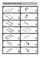
Assembly Instructions 1 1100 x 450 x 15 mm 8 1 2 847 x 425 x 15 mm 1 9 1 3 847 x 425 x 15 mm 847 x 425 x 15 mm 10 1005.
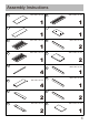
Assembly Instructions 15 754 x 320 x 12 mm 23 1 1 16 1100 x 300 x 15 mm 24 1 17 687 x 387 x 15 mm 687 x 387 x 15 mm 25 26 20 287 x 80 x 12 mm 21 500 x 80 x 12 mm 27 350 x 40 x 12 mm 28 350 x 40 x 12 mm 4 500 x 80 x 12 mm 2 1 1 29 2 22 350 x 205 x 12 mm 2 297 x 12 x 12 mm 4 350 x 40 x 12 mm 2 1 19 350 x 208 x 12 mm 1 1 18 840 x 250 x 15 mm 350 x 40 x 12 mm 2 30 350 x 207 x 12 mm 1 6
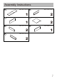
Assembly Instructions 31 825 x 207 x 12 mm 35 2 1 32 387 x 150 x 15 mm 36 1 33 350 x 103 x 12 mm 2 34 323 x 102 x 12 mm 345 x 331x 3 mm 2 37 387 x 150x 15 mm 1 350 x 103 x 12 mm 2 7
Assembly Instructions E Step 1 E E CR CR E E 6 180° CL 6 E E E 3.
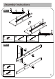
Assembly Instructions Step 3 U=U1+U2 II U I x3 U1 U2 U 290mm running x 3 Step 4 E A E A E CR 180° U1 4 E E 4 E E CR U Cam Bolt x 2 3.
Assembly Instructions E Step 5 A CL E E E CL A 2 E 3 U1 E E E U1 U Cam Bolt x 2 3.
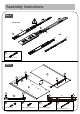
Assembly Instructions Step 7 8 8 I I I H I 9 H 10 3 H H 9 6*45mm Screw x 4 Vertical nut x 4 U1 Step 8 E A E A A A A 1 A A E A E U1 U Cam Bolt x 8 3.
Assembly Instructions Step 9 C 1 C C C C C C C B B B 6 B B 3 B B 4 B 2 Cam lock x 8 8*30mm Dowel x 8 Step 10 12 11 12
Assembly Instructions D D Step 11 D D 5 D C D C C C C C 8*30mm Dowel x 6 4*35mm Screw x 6 M Step 12 M M L M K L M M M K M K M K M 6*14mm Screw x 20 Locking caster x 2 K Caster x 3 13
Assembly Instructions E Step 13 E E N E E E N E E 16 E E N E E N E 3.5*12mm Screw x 9 hinge x 3 Step 14 E E E N E E E 16 E 3.
Assembly Instructions E Step 15 E E E E E J E E J 14 S J J 13 S E 3.5*12mm Screw x 8 S Pressure ball x 2 hinge x 4 Step 16 E E E E E 14 E E E E 13 3.
Assembly Instructions Step 17 16 16
Assembly Instructions Step 18 O O O O 15 Pivot x 4 Step 19 A 22 A A 21 A Cam Bolt x 8 x2 17
Assembly Instructions Step 20 22 19 C B 20 19 C B B C 20 21 B x2 C Cam lock x 8 8*30mm Dowel x 8 Step 21 A A A 17 A A A A 18 A Cam Bolt x 8 18
Assembly Instructions Step 22 E E G 18 E E R G R F R Hold hands x 1 4*20mm Screw x 2 E 26mm x 2 3.5*12mm Screw x 4 Step 23 E E Q E E Q 17 G G F Q Hold hands x 1 4*20mm Screw x 2 26mm x 2 E 3.
Assembly Instructions Step 24 B 21 B C B C 17 22 B C C B 21 C B C 18 Cam lock x 8 22 B B C C 8*30mm Dowel x 8 Step 25 E 18 E E 17 E E 3.
Assembly Instructions Step 26 V W V Back plate buckle x 14 W 3*14mm Screw x 14 Step 27 A A A A A 23 A Cam Bolt x 6 21
Assembly Instructions Step 28 E U2 E E 28 U2 E E 27 U2 E 24 U 3.
Assembly Instructions Step 30 C C B 26 C C B 24 F C C B 29 G C B 23 C C B 29 26 Cam lock x 6 G Hold hands x 1 8*30mm Dowel x 10 C B 4*20mm Screw x 2 Step 31 24 C C D D D 26 C C C C 29 C D 29 C 31 D 26 C C D 8*30mm Dowel x 10 4*35mm Screw x 6 23
Assembly Instructions Step 32 Step 33 P P P P P 30 P 30 P P P Pivot x 4 24
Assembly Instructions Step 34 A A A A 32 A A A A 37 Cam Bolt x 8 Step 35 D D 34 35 D D 4*35mm Screw x 8 33 x2 25
Assembly Instructions Step 36 36 x2 Step 37 B B G G B 32 B Cam lock x 8 Hold hands x 2 37 F 4*20mm Screw x 4 x2 26
Assembly Instructions Step 38 E DL E E DR E 32 37 x2 3.