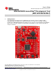
MSP430F5529 LaunchPad™ Development Tool MSP-EXP430F5529LP User's Guide Literature Number: SLAU533A September 2013 – Revised January 2014
Contents ................................................................................................................... 5 ............................................................................................................. 6 1.2 Kit Contents .............................................................................................................. 6 1.3 Out-of-Box Experience .................................................................................................. 6 2 Hardware .....
www.ti.com List of Figures 1 MSP430F5529 LaunchPad ................................................................................................ 5 2 Jumper Requirements Necessary for Software Demo ................................................................. 7 3 Storage Volume, Mounted from the MSC Interface .................................................................... 8 4 Files on the Storage Volume ...................................................................................
www.ti.com List of Tables 1 Files on the Storage Volume .............................................................................................. 8 2 eZ-FET lite LED Feedback Behavior ................................................................................... Isolation Block Connections .............................................................................................. Hardware Change Log ..........................................................................................
User's Guide SLAU533A – September 2013 – Revised January 2014 MSP430F5529 LaunchPad™ Development Tool (MSP‑EXP430F5529LP) 1 Getting Started The LaunchPad™ development tools for MSP430™ microcontrollers now have USB! The MSPEXP430F5529LP LaunchPad (or the "F5529 LaunchPad") is an inexpensive and simple evaluation module for the MSP430F5529 USB microcontroller.
Getting Started www.ti.com Rapid prototyping is a snap, thanks to 40-pin expansion headers for LaunchPad BoosterPack™ development tools and a wide range of available BoosterPack plug-in modules. You can quickly add features like wireless, displays, sensors, and much more. You can either design your own BoosterPack or choose among many already available from TI and elsewhere. The 40-pin interface is compatible with any 20-pin BoosterPack that is compliant with the standard (see Section 2.7 for details).
Getting Started www.ti.com Figure 2. Jumper Requirements Necessary for Software Demo Step 1: Install a Software Development Platform The development platform can be Code Composer Studio IDE (CCS), IAR Embedded Workbench IDE (IAR), mspgcc, or Energia open-source platform. See Section 3.2 for help choosing a platform. The out-of-box demo works without this step, but the host reports that the integrated eZ-FET lite emulator did not enumerate.
Getting Started www.ti.com Figure 3. Storage Volume, Mounted from the MSC Interface This storage volume is stored within the MSP430F5529's on-chip flash. It is small compared to most flash drives, but it is large enough for the demo's needs. The MSP430 software presents it to the host through the MSC interface. If you open the volume, you see these files: Figure 4. Files on the Storage Volume Table 1 describes the function of these files. Table 1. Files on the Storage Volume File Description Button1.
Getting Started www.ti.com To see the keyboard in action, open a text editor. If using Windows, the standard Notepad application is a good choice. (To open Notepad, click the Start button, then click Run…, type "notepad" in the Open text box, and click OK.) Make sure the window focus is on the text editor and not on another application running on the PC. Then press the S1 button on the LaunchPad to send the text in Figure 5 to Notepad. Figure 5.
Getting Started www.ti.com The rocket can take a few seconds to type out. While the MSP430 is typing this out, be sure not to change the PC's window focus outside of Notepad. If you change the focus, keystrokes will be sent to whatever application has focus, and strange things might happen on your PC! Step 5: Customize the strings Because the strings typed out by the S1 and S2 buttons originate from the Button1.txt and Button2.txt files, respectively, you can change these strings.
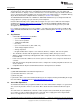
Hardware www.ti.com 2 Hardware This section describes the F5529 LaunchPad hardware. Figure 7 shows the LaunchPad, with its important features and configuration controls. These controls are described in this section.
Hardware 2.1 www.ti.com Block Diagram Figure 8 shows a functional block diagram of the board. USB Connector 5V VBUS TPS62237 5V-3.3V DC-DC Converter eZ-FET lite Emulator ESD Protection 3.3V USB USB Hub / Power USB Data 6MHz TUSB2046 Full-Speed USB Hub eZ-FET lite Emulator MCU Emulator USB 4MHz 5V VBUS 32kHz 40-pin (4x10) Boosterpack Interface Spy-Bi-Wire (SBW) Emulation Application UART 3.
Hardware www.ti.com 2.2 2.2.1 Hardware Features MSP430F5529 The MSP430F552x is one of several USB-equipped MSP430 derivative families. It offers: • 1.8-V to 3.
Hardware www.ti.com Other USB-equipped MSP430 families include the smaller F550x family and the larger F563x, F663x, F565x, and F665x families. To compare the various MSP430 derivatives, download the MSP430 Product Brochure, which is also available from http://www.ti.com/msp430. The brochure has a table that lets you see at a glance how the families compare and their pricing. This document is frequently updated as new MSP430 derivatives become available. 2.2.
Hardware www.ti.com Features of the eZ-FET lite: • USB debugging and programming interface • No need to install a driver on the host Windows or Linux PC – it loads silently • Application ("backchannel UART") virtual COM port connection with the host, over USB, up to 1 Mbaud • LEDs for visual feedback • Field-updateable firmware • Supports almost all MSP430 devices Hardware and software requirements • PC with Windows or Linux • MSP430.DLL 3.3.0.
Hardware www.ti.com The eZ-FET lite emulator itself is a composite USB device, which means that it contains two USB interfaces: • A CDC interface (virtual COM port) for the emulation function • A CDC interface (virtual COM port) for the application UART (For an explanation of USB interfaces, see the discussion in Step 2 of Section 1.3) These interfaces can be found on the host PC. As an example, Device Manager can be used for this purpose on a Windows PC. (See Section 3.
Hardware www.ti.com USB hosts supply a 5-V power rail to USB devices, called "VBUS". This is convenient for USB devices; if they only need to function while attached to a host (for example, mice or keyboards) then they may not need their own power source.
Hardware www.ti.com 6MHz TUSB2046 Full-Speed USB Hub eZ-FET lite Emulator MCU USB 4MHz eZ-FET lite Emulator ESD Protection USB USB Hub and Power USB Connector UART Isolation Jumper Block F5529 d P [ USCI_A1 Interface Figure 14. Backchannel UART Pathway On the host side, a virtual COM port for the application backchannel UART is generated when the F5529 LaunchPad enumerates on the host.
Hardware www.ti.com Also unlike the eZ-FET on the G2 LaunchPad, this eZ-FET lite supports hardware flow control, if desired. Hardware flow control (CTS and RTS handshaking) allows the target F5529 and the emulator to tell each other to wait before sending more data. At slow baud rates and with simple target applications, flow control may not be necessary.
Hardware 2.2.8 www.ti.com Isolation Jumper Block: 3.3-V and 5-V Jumpers The 5-V VBUS and 3.3-V power rails, which are sourced to the target from the emulator, travel through the isolation jumper block.
Hardware www.ti.com Note that this measurement does not include USB current, which is sourced through the 5V jumper instead. USB current levels can vary widely, depending on whether the connection is active or suspended, how much bus activity is happening, how long the cable is, and other factors. If you are trying to achieve the LPM3 values shown in the F5529 data sheet and are having trouble, download the F5529 code examples and see MSP430F552x_LPM3_01.c, adjusting the I/O settings for your application.
Hardware 2.4.1 www.ti.com External 3.3-V Power Source It is often beneficial to evaluate the LaunchPad with an external power source (see Figure 18). To see accurate system power when performing this action, it is best to disconnect all jumpers in the isolation block, so that additional power is not consumed by back-powering the emulation MCU through its I/Os. The 5-V jumper can be left populated for proper USB operation and to allow for 5 V to the target side. USB Connector DC-DC Converter 5V in 3.
Hardware www.ti.com 2.4.2 External 5-V Power Source Without USB Connection If USB connection is not required, the 5V jumper in the isolation jumper block may be left populated (see Figure 19). In this case, 3.3 V is derived through the dc-dc converter and, depending on the 3V3 jumper setting in the isolation jumper block, can power the target device as well. If using external power source for both 3.3 V and 5 V, consider recommendations for each.
Hardware 2.4.3 www.ti.com External 5-V Power Source With USB Connection In certain situations, it is advantageous to have an external 5-V source and USB connected simultaneously (see Figure 20). The USB connection may be needed for direct USB communication, backchannel UART, or to allow for programming through emulation. In this scenario, the 5V jumper in the isolation block must be disconnected to allow for the two separate 5-V sources. If using external power source for both 3.
Hardware www.ti.com 2.5 Using the eZ-FET lite Emulator With a Different Target The eZ-FET lite emulator on the F5529 LaunchPad can interface to most MSP430 derivative devices, not just the on-board F5529 target device. To do this, disconnect every jumper in the isolation jumper block. This is necessary because the emulator cannot connect to more than one target at a time over the Spy-Bi-Wire (SBW) connection. Next, make sure the target board has proper connections for Spy-Bi-Wire.
Hardware www.ti.com Hold the button down while attaching the F5529 LaunchPad to the USB host, continue to hold it for approximately one second after attaching, and then release. (This assumes the F5529 LaunchPad was unpowered prior to attaching, which allows a power-up event to occur.) The target F5529 should enumerate under USB BSL control as a HID interface. The USB BSL has its own vendor ID (VID) and product ID (PID), the codes used in USB to separate one USB product from another.
Hardware www.ti.com After this interface enumerates, a host application is needed to interface with it and issue BSL commands to access the MSP430's firmware. The MSP430 USB Developers Package includes a firmware updater application that uses the USB BSL to download programs. For its input, it uses TI-TXT object-code files. TI-TXT is a simple text-based object-code format that used with MSP430 MCUs to store and distribute compiled code. These files can be generated by CCS or IAR.
Hardware www.ti.com BoosterPack Pinout Standard Software-Configurable MSP430F5529 Pin Functions F5529 LaunchPad (!) Denotes an interrupt-capable I/O BoosterPack Pinout Standard Software-Configurable MSP430F5529 Pin Functions F5529 LaunchPad Power Analog SPI I2C General I/O Unused function Figure 23.
Hardware www.ti.com 2.8 Design Files A complete schematic is available in Section 6. All hardware design files including schematics, layout, bill of materials (BOM), and Gerber files are in a zip folder (SLAC623). This zip folder also contains the software examples, TI-TXT object-code firmware images, and documentation. The schematic's PDF is searchable to make it easier to follow signals across the multipage schematic. 2.9 Hardware Change Log Table 4.
User Experience Software 3 www.ti.com User Experience Software There are two software examples included with the F5529 LaunchPad (see Table 5) that can be found in the zip folder (SLAC623). This zip folder also contains the hardware design files and documentation. Table 5. Software Examples Demo Name USB Interface Type Description Described In… emulStorageKeyboard The out-of-box demo, or user experience, that is programmed on the F5529 LaunchPad from the factory.
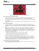
User Experience Software www.ti.com 3.2.1 CCS CCS v5.4 or higher is required. When CCS has been launched, and a workspace directory chosen, click Project and then Import Existing CCS Eclipse Project. Browse to the desired demo's project directory containing main.c. This is either simpleUsbBackchannel or emulStorageKeyboard (see Figure 24). Figure 24. Browse to Demo Project for Import Function Selecting the \CCS subdirectory also works. (The CCS-specific files are located there.
User Experience Software www.ti.com Sometimes CCS finds the project, but does not have a checkmark; this might mean that your workspace already has a project by that name. You can resolve this by renaming or deleting the existing project. (If you do not see the existing project in the CCS workspace, check the workspace's directory on the file system.) Finally, click Finish.
User Experience Software www.ti.com Table 6. Demo Project File and Directory Descriptions (continued) Name USB_app 3.4 Description Files related to USB functionality, but which are part of the application and not the USB API itself. These files handle the keyboard emulation, and implement the virtual storage volume mounted by the device. The directory also contains the USB "event handlers".
User Experience Software 3.5 www.ti.com Out-of-Box Experience: emulStorageKeyboard This is the demo that is loaded into the F5529 LaunchPad at the factory. It is described in Section 1.3. This demo is slightly more advanced than the simpleUsbBackchannel demo. The code is prolifically commented, and the following sections provide additional detail. 3.5.1 Flowchart Figure 28 shows the program flow. The following sections reference this flow.
User Experience Software www.ti.com 3.5.2 Pre-Initialization Pre-initialization refers to the activity that happens before the first line of main(). As described for the simpleUsbBackchannel example (see Section 3.6.5.1), it is often convenient during development to disable the watchdog at the beginning of execution. But for some application programs, including this demo, there's a twist. Programs that contain a large amount of allocated RAM may never reach the first line of main().
User Experience Software www.ti.com The application must also tell the USB API about the mass storage volume's media; for example, how big it is, if it is write protected, and if it is been changed recently (if removable). It does this with USBMSC_updateMediaInfo(). 3.5.4 Handling SCSI Commands The first item in the main loop is a call to USBMSC_poll().
User Experience Software www.ti.com Similarly, code checks for these other interrupt-driven events that may have occurred after the main loop checked their flags. If execution enters sleep while these flags are set, they are not handled until yet another interrupt occurs. This could cause the device to be unresponsive. For similar reasons, interrupts are disabled prior to evaluating any of these flags.
User Experience Software www.ti.com USB events are like software callbacks, functions called by the USB interrupt service routine (ISR) that the application can choose to service. These handlers are in the file usbEventHandling.c. If the event handler returns TRUE, the CPU remains awake after the USB ISR returns; this causes execution to resume from the point of LPM0 entry, if it had been sleeping there. (If it had not been sleeping, then the resumption has no effect.
User Experience Software www.ti.com Although the word "send" is an easy way to describe it, it is not quite correct. In USB, everything is initiated by the host. What actually happens with HID interfaces is that the USB device prepares a report and makes it available to the host. Then, on a regular interval, the host polls the device to see if it has any reports ready. In the Descriptor Tool, this particular interface was set to have the fastest possible polling interval: 1 ms.
User Experience Software 3.5.9 www.ti.com Properly Handling USB Unplug Events In USB, it is important to consider that the bus may suddenly become unavailable. For example, the USB cable can be removed by the user at any time. If the developer does not keep this in mind, it is easy to write code that can hang up indefinitely when it happens. For example, suppose the bUsbSendComplete flag had been polled until it was set to TRUE.
User Experience Software www.ti.com x Terminal App Terminal App ]uo l Z vv o Z}[ CDC Interface Backchannel UART, via eZ-FET lite emulator x x x x x x x USB Host PC simpleBackchannelEcho Example F5529 LaunchPad o] ]}v[ h^ Backchannel UART Figure 31. Movement of Data in simpleUsbBackchannel: CDC 3.6.2 Installing the CDC Interface Now, build and run the example. When you do this for the first time on a Windows PC, Windows asks for an INF file (simpleUsbBackchannel.
User Experience Software www.ti.com Figure 32. simpleUsbBackchannel's USB Virtual COM Port, Needing a Driver In the dialog box, browse to the INF file in the simpleUsbBackchannel directory. If more help is needed to install the CDC interface, see the Examples Guide in the MSP430 USB Developers Package, which contains a more complete description. Linux PCs do not have this requirement. CDC interfaces enumerate silently as TTY devices in the \dev directory.
User Experience Software www.ti.com 3.6.3 Operating the Example When installation is complete, both COM ports are available. On a Windows PC, Device Manager runs (see Figure 33) (see Section 3.7 for how to open Device Manager). Figure 33. Device Manager After Both Ports are Enumerated The UART backchannel's port name is "MSP Application UART1". The USB CDC interface for the simpleUsbBackchannel application is "F5529LP simpleUsbBackchannel".
User Experience Software www.ti.com On the F5529 LaunchPad, the backchannel UART is implemented with the USCI_A1 module. The RTS and CTS flow control signals are implemented on the P6.7 and P1.7 I/O pins, respectively. All of these locations are hardwired on the F5529 LaunchPad and are independent from the 40-pin BoosterPack header. Table 7 shows some constants in bcUart.h that define the library's behavior. Table 7.
User Experience Software www.ti.com Although primarily related to CPU speed, the device data sheet also shows that during operation of the USB PLL (that is, during an active USB connection), VCORE must be set to 2 or 3, the highest two levels. Because the demo's use of an 8-MHz clock does not require a setting of 3, the PMMCOREV register is set to 2. 3.6.5.3 Configuring Clocks MSP430 applications typically use a fast clock and a slow clock.
User Experience Software 3.6.5.4 www.ti.com Configuring Ports In the function initPorts(), all of the I/Os are configured to drive out-low. Later, in bcUartInit(), the USCI_A1 module's UART pins will be configured for the backchannel UART. The purpose of initPorts() is to eliminate floating inputs. These are a source of unexpected power draw, so it is a good practice to either drive all I/Os out or make sure any inputs are being pulled high or low from the outside.
User Experience Software www.ti.com When data is sent over a UART, communication generally happens quickly, because it is low-level and has essentially no overhead. After a byte is written to the TXBUF register, the time is very brief before TXBUF is ready to send the next byte. Therefore, bcUartSend() does not return until all bytes are sent.
User Experience Software www.ti.com x HID Demo App Terminal App ]uo l Z vv o Z}[ HID-Datapipe Interface Backchannel UART, via eZ-FET lite emulator x x x x x x x USB Host PC simpleBackchannelEcho Example F5529 LaunchPad o] ]}v[ h^ Backchannel UART Figure 34. Movement of Data in simpleUsbBackchannel: HID-Datapipe 3.7 Starting Device Manager Device Manager is very useful for determining what USB interfaces have enumerated on the host.
User Experience Software www.ti.com If Windows asks if you want to allow the program to make changes to your computer, click Yes; however, Device Manager is very useful for viewing purposes without having to change anything (see Figure 36). Figure 36. Device Manager The groups in Device Manager that are relevant to MSP430 USB work include: • Ports (for virtual COM ports) • Human Interface Devices (for HID interfaces).
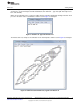
Additional Resources www.ti.com 4 Additional Resources 4.1 LaunchPad Websites More information about the F5529 LaunchPad, supported BoosterPacks, and available resources can be found at: • F5529 LaunchPad tool page: resources specific to this particular LaunchPad • TI's LaunchPad portal: information about all LaunchPads from TI for all MCUs • LaunchPad wiki: design resources and example projects from the community Figure 37. F5529 LaunchPad With DLP-7970ABP NFC BoosterPack 4.
Additional Resources www.ti.com You can obtain the MSP430 USB Developers Package in these ways: • Download and install CCS, which contains MSP430Ware if the appropriate box is checked during installation. • Download it as part of MSP430Ware • Download it as a separate download If you have already installed CCS, you probably already have the USB Developers Package. Click the View menu, click TI Resource Explorer, and go to the USB Developers Package under Libraries.
Additional Resources www.ti.com Figure 38. USB Examples in the USB Developers Package The Resource Explorer also has a wizard for creating your own empty USB project (see Figure 39).
Additional Resources www.ti.com Figure 39. TI Resource Explorer: Create a New USB Project Wizard Inside TI Resource Explorer, click Libraries, then click USB Developers Package, and finally click Example Projects. Click Empty USB Project. This feature is only found in MSP430Ware v1.40.01.44 and later, which is distributed in CCS v5.5. 4.6 F5529 Code Examples This is a set of very simple code examples that demonstrate how to use the MSP430's entire set of peripherals: ADC12, Timer_A, Timer_B, and so on.
FAQs 4.9 www.ti.com Community at Large Many online communities focus on the MSP430 – for example, http://www.43oh.com. You can find additional tools, resources, and support from these communities. 5 FAQs Q: I can't get the backchannel UART to connect.
FAQs www.ti.com Q: I'm trying to power the LaunchPad from a USB power supply (not an actual USB host), and it is not working. Does the LaunchPad not support this? Unfortunately Rev1.4 does not. USB hubs typically shouldn't enable power to their downstream devices until the hubs themselves enumerate on the host, and that's what the TUSB2046 on the Rev1.4 F5529 LaunchPad does through the TPS2041B power switches. If the hub never enumerates, power is not provided to the target F5529.
Schematics Schematics 1 2 3 XT2 Q4 CSTCR4M00G15L99 1 4 GND 3 +3V3 BSL GND +3V3 C15 220n GND S5 C16 220n 2 RESET C27 R14 100R + GND Speed TARGET_DM TARGET_DP 1k4 R16 1M 470n GND D P8.2 P2.3/TA2.0 P2.4/TA2.1 P2.5/TA2.2 P2.0/TA1.1 P2.1/TA1.2 P2.2/TA2CLK/SMCLK DVCC1 PUR PU.0/DP PU.1/DM VSSU P3.3/UCA0TXD/UCA0SIMO P8.1 P3.0/UCB0SIMO/UCB0SDA P8.0 P3.1/UCB0SOMI/UCB0SCL AVSS1 P3.2/UCB0CLK/UCA0STE P5.5/XOUT P2.7/UCB0STE/UCA0CLK P5.4/XIN P2.
Schematics www.ti.com 1 2 3 4 40 pin BoosterPack Headers P6.5 P3.4 P3.3 P1.6 P6.6 P3.2 P2.7 P4.2 P4.1 1 3 5 7 9 11 13 15 17 19 2 4 6 8 10 12 14 16 18 20 100n GND P6.0 P6.1 P6.2 P6.3 P6.4 P7.0 P3.6 P3.5 GND B 1 3 5 7 9 11 13 15 17 19 2 4 6 8 10 12 14 16 18 20 User Buttons JP2 +3V3 JP3 GND GND P1.1 JP6.1 TXD JP6.2 RXD JP6.3 CTS P1.7 >> JP6.4 RTS P6.7 << 1 2 P1.
Schematics www.ti.com 1 2 2 eZ-FET lite Emulator GND P6.5/CB5/A5 P6.6/CB6/A6 P6.7/CB7/A7 100n 220n 220n GND GND GND EZFET_PUR C101 D R105 1k4 EZFET_PU.1/DM EZFET_PU.
Schematics www.ti.
Revision History www.ti.com Revision History Changes from Original (September 2013) to A Revision ............................................................................................... Page • • • • • • • • • • • • • • • • Changed description of COM port access ........................................................................................... Changed Figure 13 .....................................................................................................................
IMPORTANT NOTICE Texas Instruments Incorporated and its subsidiaries (TI) reserve the right to make corrections, enhancements, improvements and other changes to its semiconductor products and services per JESD46, latest issue, and to discontinue any product or service per JESD48, latest issue. Buyers should obtain the latest relevant information before placing orders and should verify that such information is current and complete.